
User`s guide


4- 24 Agilent EasyEXPERT User’s Guide Vol. 1, Edition 1
Function Details
C-V Sweep Measurement
Four-Terminal Pair Configuration
Generally, any mutual inductance, interference of the measurement signals, and
unwanted residual factors in the connection method incidental to ordinary
termination methods will have significant effects on the measurements, especially at
a high frequency. The MFCMU employs the four-terminal pair (4TP) measurement
configuration which permits easy, stable, and accurate measurements and avoids the
measurement limitations inherent to such factors.
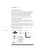
Figure 4-13 shows the four-terminal pair measurement principle. The measurement
terminals consist of the following four coaxial connectors.
• Hcur: High current
• Hpot: High potential
• Lpot: Low potential
• Lcur: Low current
Figure 4-13 Four-Terminal Pair Measurement Principle
The four-terminal pair measurement method has the advantage in both low and high
impedance measurements. The outer shield conductors work as the return path for
the measurement signal current (they are not grounded). The same current flows
through both the center conductors and outer shield conductors (in opposite
directions), but no external magnetic fields are generated around the conductors (the
magnetic fields produced by the inner and outer current completely cancel each
other). Because the measurement signal current does not develop an inductive
magnetic field, test leads do not contribute additional errors due to self or mutual
inductance between the individual leads.
'87
0XOWLIUHTXHQF\&08
9
+FXU
+SRW
$
/FXU
/SRW
$XWREDODQFHEULGJH
9LUWXDOJURXQG
6\VWHPJURXQG
,[
,[
9[
9[
,[
,[
2XWHUVKLHOGRU*XDUG