
User`s guide


4- 22 Agilent EasyEXPERT User’s Guide Vol. 1, Edition 1
Function Details
C-V Sweep Measurement
Measurement Parameters
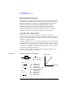
MFCMU performs impedance measurement, calculates parameters shown in Table
4-2, and returns the calculated data. A combination can be selected for the return
data. For example and for your reference, select the parallel measurement mode
(Cp-G or Cp-D) for the low capacitance measurements (100 or more of
impedance), and select the series measurement mode (Cs-Rs) for the high
capacitance measurements (100 or less of impedance). Because the low
capacitance yields high reactance, which implies that the effect of the parallel
resistance has relatively more significance than that of series resistance.
About Impedance Measurements
All circuit components, resistors, capacitors, or inductors, have parasitic
components, for example unwanted resistance in capacitors, unwanted resistance in
inductors, and unwanted inductance in resistors. Thus simple components should be
modeled as complex impedances.
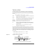
Impedance definitions and vector representation of impedance are shown in Figure
4-11. Impedance Z is the total opposition that a circuit or device offers to the flow of
alternating current at a given frequency. Z contains a real and an imaginary part, and
it is expressed in rectangular form as resistance R and reactance X, or in polar form
as magnitude of impedance |Z| and phase
.
In addition to these parameters, the quality factor Q and dissipation factor D are
used to describe the quality of components.
Figure 4-11 Impedance and Parameter Calculation
= 5M; _=_aP
_=_ 5;
P WDQ
5
_;_
5 5V
=
,
9
=
,
9
; J\I/
4
'
5
_;_
=LPSHGDQFH
5UHVLVWDQFH
;UHDFWDQFH
PSKDVHGHJUHHRUUDGLDQ
5VVHULHVUHVLVWDQFH
IIUHTXHQF\+]
/LQGXFWDQFH+
4TXDOLW\IDFWRU
'GLVVLSDWLRQIDFWRU
5HDOSDUW
,PDJLQDU\SDUW
_=_
P
M;
5
,FXUUHQW$
9YROWDJH9