
User`s guide


4- 8 Agilent EasyEXPERT User’s Guide Vol. 1, Edition 1
Function Details
I/V Sweep Measurement
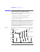
Synchronous Sweep Measurement
For synchronous sweep measurement, you set up a synchronous sweep source
(VAR1’) in addition to a primary sweep source (VAR1).
The relationship between the output of primary and synchronous sweep sources is
determined by the following equation:
synchronous output = primary output ratio + offset
The synchronous output determined by above equation must not exceed the output
range of synchronous sweep source.
The following parameter settings are effective for the VAR1’ sweep source.
• Direction (Single or Double)
• Linear/Log
The following setup is required to perform the synchronous sweep measurements.
See
“I/V Sweep” on page 2-4 for the GUI.
1. Select the following on the Channel Setup tab screen.
• Select VAR1 for the Function of the SMU used for VAR1.
• Select VAR1’ for the Function of the SMU used for VAR1’.
• Select V, VPULSE, or COMMON for the Mode of current monitor SMU, or
I or IPULSE for voltage monitor SMU. Pulse is available only for one SMU.
Mode of VAR1 and VAR1’ must be the same, voltage or current.
2. Set the VAR1 channel as shown in “Basic Sweep Measurement”.
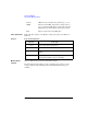
3. Specify the following parameters for VAR1’ on the Measurement Setup tab
screen.
Offset Offset between outputs of primary and synchronous sweep
sources.
Ratio Ratio between outputs of primary and synchronous sweep
sources.
Compliance Compliance value of synchronous sweep source. Allowable
range of compliance depends on the compliance range of
synchronous sweep source.
Pwr Comp (Optional) Power compliance value of synchronous sweep
source. Allowable range of power compliance depends on
the power compliance range of synchronous sweep source.