
User`s guide


2- 64 Agilent EasyEXPERT User’s Guide Vol. 1, Edition 1
Classic Test Definition
SPGU Pulse Setup Window
SPGU setup view
order
Up Moves the selected channel setup upward.
Down Moves the selected channel setup downward.
Changes are effective only for the display on the SPGU Pulse Setup window and not
memorized. They are not applied to the Channel Setup.
Load Z This button opens the “Load Z Setup Window” used to set the load impedance of the
DUT (device under test) connected to the SPGU channel. The SPGU will
automatically adjust the output voltage by using this value, and output the voltage
close to the specified pulse base and peak values.
Pulse Switch This button opens the “Pulse Switch Setup Window” used to set the pulse switch
operation. The pulse switch is used to set the open condition of the SPGU output
channel. The pulse switch is more durable than mechanical relays, and is better
suited for frequent switching applications.
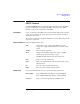
Figure 2-3 SPGU Pulse Setup Parameters
Period
Width
V/10
V/10
Leading
Base
Peak
V: Pulse level
Delay
Delay
V/10
V/10
Trailing
Start
Width-sw
Delay-sw
Pulse switch
Normally open
Close
Close
Open
Delay-sw