
User`s guide


2- 62 Agilent EasyEXPERT User’s Guide Vol. 1, Edition 1
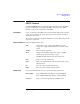
Classic Test Definition
SPGU Control
Progress Monitor Provides the following check boxes used to set the Data Display window displayed
while the SPGU channel output is applied.
Graph: % of
Progress
Check this box to display the Percent of Progress vs. Time plot.
List: Time Data Check this box to display the Time data list.
No data may be displayed on the Data Display window if the SPGU output time is
too short. The progress monitor will be used for long duration outputs, for example
when the duration is longer than 30 seconds.
Advanced Setup Window for SPGU Control
This window is opened by clicking the Advanced button on the SPGU Control
screen, and is used to set the following functions of the SPGU channel.
After Measurement
Setting
Sets the bias hold function used to decide the channel output after the SPGU output
operation.
Bias Hold after
Measurement
Bias hold function ON or OFF
If the bias hold function is OFF, the channel stops the output immediately after the
SPGU output operation.
If the function is ON, the channel maintains the base voltage output (in the VPULSE
mode) or the initial voltage output (in the ALWG mode) between a SPGU output
operation and the next operation performed in the repeat execution or quick test.
Channel initialization occurs at the beginning of the next operation.
Semiconductor
Relays (16440A
SMU/PG Selector)
Sets the CH1/CH3 status (DEFAULT or PGU OPEN) of Agilent 16440A SMU/PGU
selector (B1500A-A04). To use this function, set the DEFAULT setting to Always
SMU or Normally PGU (AUX) by using the SMU/PG Selector tab screen on the
Configuration window before starting the SPGU output.
CH1 CH1 status, DEFAULT or PGU OPEN.
CH3 CH3 status, DEFAULT or PGU OPEN.
CH1 represents channel 1 on the first selector and CH3 represents channel 1 on the
second selector. See
“SMU/PG Selector” on page 4-49 for details on the selector.
Agilent 16445A selector adapter is needed for connecting the SMU/PGU selector.