Agilent E7501A Arbitrary Analog Signal Development System (...
Notice The information contained in this document is subject to change without notice. Agilent Technologies makes no warranty of any kind with regard to this material, including, but not limited to, the implied warranties of merchantability and fitness for a particular purpose. Agilent Technologies shall not be liable for errors contained herein or for incidental or consequential damages in connection with the furnishing, performance, or use of this material.
Warranty Certification Agilent Technologies certifies that this product met its published specifications at the time of shipment from the factory. Agilent Technologies further certifies that its calibration measurements are traceable to the United States National Institute of Standards and Technology (NIST, formerly NBS), to the extent allowed by the Institute’s calibration facility, and to the calibration facilities of other International Standards Organization members.
LIMITATION OF WARRANTY. The foregoing warranty shall not apply to defects resulting from improper or inadequate maintenance by Buyer, Buyer-supplied software or interfacing, unauthorized modification or misuse, operation outside of the environmental specifications for the product, or improper site preparation or maintenance. NO OTHER WARRANTY IS EXPRESSED OR IMPLIED. AGILENT TECHNOLOGIES SPECIFICALLY DISCLAIMS THE IMPLIED WARRANTIES OR MERCHANTABILITY AND FITNESS FOR A PARTICULAR PURPOSE.
Service and Support Any adjustment, maintenance, or repair of this product must be performed by qualified personnel. Contact your customer engineer through your local service center. You can find support information on the web at http://www.tm.agilent.
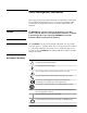
Safety and Regulatory Information Review this product and related documentation to familiarize yourself with safety markings and instructions before you operate the instrument. This product has been designed and tested in accordance with international standards. WARNING The WARNING notice denotes a hazard. It calls attention to a procedure, practice, or the like, that, if not correctly performed or adhered to, could result in personal injury.
Safety Earth Ground This is a Safety Class I product (provided with a protective earthing terminal). An uninterruptible safety earth ground must be provided from the main power source to the product input wiring terminals, power cord, or supplied power cord set. Whenever it is likely that the protection has been impaired, the product must be made inoperative and secured against any unintended operation.
Typeface Conventions • Used to emphasize important information: Use this software only with the Agilent Technologies xxxxxX system. • Used for the title of a publication: Refer to the Agilent Technologies xxxxxX System-Level User’s Guide. • Used to indicate a variable: Type LOAD BIN filename. Instrument Display • Used to show on-screen prompts and messages that you will see on the display of an instrument: The Agilent Technologies xxxxxX will display the message CAL1 SAVED.
In This Book... In this book, you will learn about: • • • • Installation of Hardware and Software Performing Manual Acceptance Tests Using SCPI Interfaces Specifications and Characteristics This book prepares you for your first steps in using the Agilent E7501A arbitrary analog signal developer.
How to proceed… First, review the hardware and software requirements for using this product. After installing the Agilent E7501A arbitrary analog signal developer software, start the program and become familiar with the features available on the main GUI, various pull-down menus, dialog boxes, and the various views available. This software is used to produce signals with AM, FM, and Pulse modulations and save all information about the signal in what is referred to as a Signal Plan.
Contents Notice . . . . . . . . . . . . . . . . . . . . . . . . . . . . . . . . . . . . . . . . . . . . . . . . . . . . . ii In This Book... . . . . . . . . . . . . . . . . . . . . . . . . . . . . . . . . . . . . . . . . . . . . . . ix 1. Installation and Configuration Hardware and Software Requirements . . . . . . . . . . . . . . . . . . . . . . . . . . . 1-2 Step 1. Unpacking the Agilent E7501A System . . . . . . . . . . . . . . . . . . . . 1-3 Step 2. Installing the System Hardware . . . . . . . . . .
Test 6. Verify Synchronization of the Racal 3153 . . . . . . . . . . . . . . . . . 2-16 Description . . . . . . . . . . . . . . . . . . . . . . . . . . . . . . . . . . . . . . . . . . . . 2-16 Equipment Required . . . . . . . . . . . . . . . . . . . . . . . . . . . . . . . . . . . . . 2-16 3. Using SCPI Interfaces Overview of SCPI Interfaces . . . . . . . . . . . . . . . . . . . . . . . . . . . . . . . . . . E7501A SCPI Assistant . . . . . . . . . . . . . . . . . . . . . . . . . . . . . . . . . . .
1 Installation and Configuration Preconfigured System A preconfigured system includes a computer shipped from Agilent Technologies with all required hardware and software pre installed. This chapter helps guide you though the process of installing both the hardware (if you did not order a preconfigured system) and the Agilent E7501A arbitrary analog signal developer software. A set of acceptance tests are also included at the end of this installation process.
Installation and Configuration Hardware and Software Requirements Hardware and Software Requirements • • • • • • Pentium microprocessor (400 MHz or higher recommended) • One of the following Slot 0 modules: Windows NT 4.
Installation and Configuration Step 1. Unpacking the Agilent E7501A System Step 1. Unpacking the Agilent E7501A System 1. Unpack and inspect the shipping container and its contents thoroughly to ensure that nothing was damaged during shipment. If the container or packing material is damaged, the contents should be checked both mechanically and electrically. If the contents are damaged or defective, contact your nearest Agilent Technologies Sales and Service office.
Installation and Configuration Step 2. Installing the System Hardware Step 2. Installing the System Hardware NOTE If you ordered a preconfigured system, skip this step and proceed to “Step 5. Starting the Agilent E7501A Software” on page 1-20. CAUTION Do not turn power on to the C-size VXI mainframe until all VXI modules have been installed and you have made all peripheral connections to the Slot 0 module being used.
Installation and Configuration Step 2. Installing the System Hardware 6. Depending on the Slot 0 module being used, perform one of the following two procedures: “If using a VXI Embedded PC Controller as the Slot 0 module:” on page 1-5 “If NOT using a VXI Embedded PC Controller as the Slot 0 module:” on page 1-6 If using a VXI Embedded PC Controller as the Slot 0 module: a. Turn power ON to the C-size VXI mainframe. b.
Installation and Configuration Step 2. Installing the System Hardware If NOT using a VXI Embedded PC Controller as the Slot 0 module: a. Set up a Windows NT computer with Service Pack 5 or higher that has a CD-ROM drive and a minimum of 128 MB or RAM. b. Turn power OFF to the Windows NT computer and install the PCI interface card being used.
Installation and Configuration Step 3. Installing the Agilent E7501A Software Step 3. Installing the Agilent E7501A Software NOTE If you ordered a preconfigured system, skip this step and proceed to “Step 5. Starting the Agilent E7501A Software” on page 1-20. 1. Insert the Agilent E7501A arbitrary analog signal developer CD-ROM. If the CD does not auto install, the Setup.exe file can be executed from the Windows NT Start task bar by selecting: Start/Run and typing D:\Setup.
Installation and Configuration Step 3. Installing the Agilent E7501A Software Use Demo Mode or select a Slot 0 Module • If Demonstration Mode is selected, no I/O libraries are required and the Agilent E7501A arbitrary analog signal developer software can be used without hardware. If You Select a Slot 0 Module • If Slot 0 is selected to be an Agilent E8491B IEEE-1394 PC Link to VXI, the Agilent I/O Libraries are installed.
Installation and Configuration Step 3. Installing the Agilent E7501A Software g. Reboot the Windows NT computer and VXI mainframe so that changes take effect. h. Run the program Resman [VXI Resource Manager] and verify that the Slot 0 module being used is found. Resman is available from the Windows NT Start task bar by selecting: Start/Programs/National Instruments VXI/Resman.
Installation and Configuration Step 4. Configuring Hardware/Software Assets Step 4. Configuring Hardware/Software Assets NOTE If you ordered a preconfigured system, skip this step and proceed to “Step 5. Starting the Agilent E7501A Software” on page 1-20. Understanding the Asset Manager Before using the Agilent E7501A arbitrary analog signal developer, you must configure a Stimulus Server.
The following procedures demonstrate how to use the Asset Manager to configure a Stimulus Server with one RF Source and three Modulation Sources that deliver AM, FM, and Pulse modulations. Following these procedures are some optional procedures that demonstrate how to configure other additional assets, and how to add or remove assets from a configuration.
Installation and Configuration Step 4. Configuring Hardware/Software Assets Selecting a Configuration Select either the Agilent E7501A or Demo configuration. If you select the Agilent E7501A as the Current Configuration , you must configure a Stimulus Server with a minimum of one RF Source and zero or more Modulation Sources. If you do not have any hardware assets connected to the computer that is running this software, you can set the Current Configuration to Demo.
Installation and Configuration Step 4. Configuring Hardware/Software Assets Configuring an RF Source 1. From the list of assets in the left-hand window pane, select RF Source. A dialog box similar to the following appears. The left-hand window pane is a tree view of assets that can be selected. The right-hand window pane shows information related to a selected asset. 2. Select an RF Source such as the Agilent/HP E6432 RF Source. 3.
Installation and Configuration Step 4. Configuring Hardware/Software Assets To Edit the VISA Library Field Select the VISA Library field and select either Agilent Technologies or National Instruments from the drop-down selection box. The selection that you make is dependent on the Slot 0 module being used with your system.
Installation and Configuration Step 4. Configuring Hardware/Software Assets Configuring a Modulation Source 1. From the list of assets in the left-hand window pane, select Modulation Source. A dialog box similar to the following appears. The left-hand window pane is a tree view of assets that can be selected. The right-hand window pane shows information related to a selected asset. 2. Select an AM modulation source such as the RI3153 AM Mod Source.
Installation and Configuration Step 4. Configuring Hardware/Software Assets To Edit the Channel Field Select the Channel field and select the channel from the drop-down selection box that is to be used with this asset. CAUTION The following table shows the default channel that is used with each output of a Racal 3153 waveform generator. When changes are made to the channel field, the corresponding cabling on the front panels must also be changed.
Installation and Configuration Step 4. Configuring Hardware/Software Assets (Optional) Adding a Hardware/Software Asset 1. Click the Add Asset icon ( ). 2. Click the down arrow to expose all asset roles (different categories of hardware/software assets) that are available in the currently selected configuration. As an example, we could add an RF Source as follows: 1. Click the Add Asset icon. 2.
Installation and Configuration Step 4. Configuring Hardware/Software Assets 4. Edit the name that you would like assigned to the newly added asset by typing in the Asset Name field. When finished editing the name, click OK. 5. The left-hand window pane should now show the newly added asset as an RF Source that can be selected and used by the current configuration. The right-hand window pane shows information related to the selected RF Source.
Installation and Configuration Step 4. Configuring Hardware/Software Assets (Optional) Removing a Hardware/Software Asset When the Configuration view is selected, the left-hand window pane is a tree view of available assets. The right-hand window pane shows information related to a selected asset. 1. Select the general category (asset role) that an asset is to be removed from by clicking the plus sign. 2. Select an asset to remove from the list that is exposed. 3. Click the Delete Asset icon ( NOTE ).
Installation and Configuration Step 5. Starting the Agilent E7501A Software Step 5. Starting the Agilent E7501A Software 1. Click the Start menu, point to Programs, point to Agilent Signal Studio, point to E7501A Signal Development System, point to and click E7501A Signal Developer. 2. The Agilent E7501A arbitrary analog signal developer software should open and be ready for use. At this point, an Acceptance Test Procedure (ATP) may be performed.
2 Performing Acceptance Test Procedures In this chapter, you will learn about: • Performing Acceptance Test Procedures After satisfying the requirements and steps detailed in Chapter 1, “Installation and Configuration””, the following manual Acceptance Test Procedure (ATP) may be performed. Performing an ATP is not required and is provided and intended as a functionality check only; it is not intended for testing against customer specifications.
Performing Acceptance Test Procedures Test 1. CW Frequency and Power Test 1. CW Frequency and Power Description During this test, the system is set to two different frequencies at two different power levels, and the output signal is measured with a spectrum analyzer. Equipment Required • • Agilent E7501A arbitrary analog signal developer Agilent 8563E spectrum analyzer Equipment Setup NOTE All test equipment requires a 30 minute warm-up period to ensure warranted performance.
Performing Acceptance Test Procedures Test 1. CW Frequency and Power Step 2. Agilent E7501A Summary Agilent E7501A Details Reset 1. From the pull down View menu, select Reset View Settings and Windows. Reference = External 2. From the RF Source Control view, select Reference and set it to External. Frequency = 1 GHz 3. From the RF Source Control view, select Frequency Units and set it to GHz. 4. From the RF Source Control view, highlight the Frequency field and enter 1 using the keyboard.
Performing Acceptance Test Procedures Test 1. CW Frequency and Power Step 4. Agilent E7501A Summary Agilent E7501A Details Frequency = 10 GHz 1. From the RF Source Control view, highlight the Frequency field and enter 10 using the keyboard. Agilent 8563E Summary Agilent 8563E Details Frequency = 10 GHz 1. Press the Frequency front panel key and enter 10 GHz. Marker, Peak Search 2. Press the Mkr and Peak Search front panel keys. Record Marker value for 10 GHz 3.
Performing Acceptance Test Procedures Test 2. AM Accuracy Test 2. AM Accuracy Description This test is used to verify that AM modulation is working correctly. The Agilent E6432A microwave synthesizer is configured for linear AM and a spectrum analyzer is used to measure sidebands. The AM output of the Racal 3153 arbitrary waveform generator drives the Agilent E6432A microwave synthesizer AM input.
Performing Acceptance Test Procedures Test 2. AM Accuracy Step 2. Agilent E7501A Summary Agilent E7501A Details Reset 1. From the pull down View menu, select Reset View Settings and Windows. Reference = External 2. From the RF Source Control view, select Reference and set it to External. Frequency = 10 MHz 3. From the RF Source Control view, select Frequency Units and set it to MHz. 4. From the RF Source Control view, highlight the Frequency field and enter 10 using the keyboard. Power = 0 dBm 5.
Performing Acceptance Test Procedures Test 2. AM Accuracy Step 3. Agilent E7501A Summary Agilent E7501A Details Frequency = 20 GHz 1. From the RF Source Control view, highlight the Frequency field and enter 20 using the keyboard. Agilent 8563E Summary Agilent 8563E Details Frequency = 20 GHz 1. Press the Frequency front panel key and enter 20 GHz. Marker, Peak Search 2. Press the Mkr and Peak Search front panel keys. Marker Delta, Next Peak 3.
Performing Acceptance Test Procedures Test 3. FM Accuracy Test 3. FM Accuracy Description This test is used to verify that FM modulation is working correctly. The Agilent E6432A microwave synthesizer and the Racal 3153 arbitrary waveform generator are configured for a modulation index of 2.404 which is approximately a null of the Bessel function Jo. The amplitude of the function generator is varied until the carrier being monitored on the spectrum analyzer is a minimum.
Performing Acceptance Test Procedures Test 3. FM Accuracy Step 2. Agilent E7501A Summary Agilent E7501A Details Reset 1. From the pull down View menu, select Reset View Settings and Windows. Reference = External 2. From the RF Source Control view, select Reference and set it to External. Frequency = 10 MHz 3. From the RF Source Control view, select Frequency Units and set it to MHz. 4. From the RF Source Control view, highlight the Frequency field and enter 10 using the keyboard. Power = 0 dBm 5.
Performing Acceptance Test Procedures Test 3. FM Accuracy Step 3. Agilent E7501A Summary Agilent E7501A Details Frequency = 20 GHz 1. From the RF Source Control view, select Frequency Units and set it to GHz. 2. From the RF Source Control view, highlight the Frequency field and enter 20 using the keyboard. Agilent 8563E Summary Agilent 8563E Details Frequency = 20 GHz 1. Press the Frequency front panel key and enter 20 GHz. Marker, Peak Search 2. Press the Mkr and Peak Search front panel keys.
Test 4. Pulse Modulation Level Accuracy Description The Agilent E6432A microwave synthesizer and the Agilent E7501A arbitrary analog signal developer is configured for pulse modulation. A spectrum analyzer is used in zero span to measure the amplitude of the pulse envelope. This measured value is compared to the CW amplitude with pulse modulation turned off. Depending on the model of spectrum analyzer used, the Pulse Repetition Frequency (PRF) may need to be decreased to measure the pulse.
Performing Acceptance Test Procedures Test 4. Pulse Modulation Level Accuracy Step 2. Agilent E7501A Summary Agilent E7501A Details Reset 1. From the pull down View menu, select Reset View Settings and Windows. Reference = External 2. From the RF Source Control view, select Reference and set it to External. Frequency = 1 GHz 3. From the RF Source Control view, select Frequency Units and set it to GHz. 4. From the RF Source Control view, highlight the Frequency field and enter 1 using the keyboard.
Performing Acceptance Test Procedures Test 4. Pulse Modulation Level Accuracy Step 3. Agilent E7501A Summary Agilent E7501A Details Frequency = 20 GHz 1. From the RF Source Control view, select Frequency Units and set it to GHz. 2. From the RF Source Control view, highlight the Frequency field and enter 20 using the keyboard. Agilent 8563E Summary Agilent 8563E Details Frequency = 20 GHz 1. Press the Frequency front panel key and enter 20 GHz. Marker, Peak Search 2.
Performing Acceptance Test Procedures Test 5. Verify Hopping with Two Pulse Modulated Signals Test 5. Verify Hopping with Two Pulse Modulated Signals Description This test uses a “canned waveform” that hops slowly between two pulse modulated signals. The canned waveform is supplied in the form of a Signal Plan that is loaded, compiled, and played. The Signal Plan creates a pulse list with four pulses and a hop list with two frequency values.
Performing Acceptance Test Procedures Test 5. Verify Hopping with Two Pulse Modulated Signals Step 2. Agilent E7501A Summary Agilent E7501A Details Reset 1. From the pull down View menu, select Reset View Settings and Windows. Open a Signal Plan 2. From the pull down File menu, select Open. 3. In the browser window that opens, navigate to the folder C:\Program Files\Agilent\Measurement and Stimulus Subsystems\FreqHopAndPulse.ssp.
Performing Acceptance Test Procedures Test 6. Verify Synchronization of the Racal 3153 Test 6. Verify Synchronization of the Racal 3153 Description This test is used to verify synchronization between all three channels of the Racal 3153 arbitrary waveform generator. Equipment Required • • NOTE Agilent E7501A arbitrary analog signal developer Agilent 8563E spectrum analyzer A different negative detector may be used depending upon the frequency range of the external leveling loop configuration.
3 Using SCPI Interfaces In this chapter, you will learn about: • • “Using the E7501A SCPI Assistant” on page 3-19 “Using the E7501A SCPI Interface” on page 3-27 “Understanding the E7501A SCPI Interface” on page 3-27 “Making a Connection” on page 3-28 “Configuring a VXI-11 Connection” on page 3-29 “Configuring a Telnet, Sockets, or RS-232 Connection” on page 3-40 How to proceed… First, after you have decided to use SCPI commands to control your hardware, select either the E7501A SCPI assistant,
Using SCPI Interfaces Overview of SCPI Interfaces Overview of SCPI Interfaces In addition to the Agilent E7501A arbitrary analog signal developer user interface, your hardware can be controlled through either or both of the following SCPI interfaces. E7501A SCPI Assistant The E7501A SCPI assistant, through its own GUI, takes input from a person. It’s primarily a development aid that provides an interface for both testing and demonstration of SCPI commands.
Using SCPI Interfaces Using the E7501A SCPI Assistant Using the E7501A SCPI Assistant Agilent E7501A Getting Started 3-19
Using SCPI Interfaces Using the E7501A SCPI Assistant To Start the E7501A SCPI Assistant 1. Click the Start menu, point to Programs, point to Agilent Signal Studio, point to E7501A Signal Development System, point to and click E7501A SCPI Assistant.
Using SCPI Interfaces Using the E7501A SCPI Assistant E7501A SCPI Assistant GUI The E7501A SCPI assistant consists of the following main sections: • • • • SCPI Command Entry Box Quick Reference Guide Selection Box Query Response Box Indicators and Related Functions Agilent E7501A Getting Started 3-21
Using SCPI Interfaces Using the E7501A SCPI Assistant SCPI Assistant SCPI Command Entry Box The SCPI Command Entry Box allows you to enter one or more SCPI commands with their parameters, and send them to the Agilent E7501A arbitrary analog signal development system. Multiple SCPI commands can be sent by separating commands with semicolons.
Using SCPI Interfaces Using the E7501A SCPI Assistant SCPI Assistant Query Response Box The Query Response Box displays all returned responses that are generated from SCPI commands being sent. To clear the Query Response Box 1. Click the Clear button ( Query Response Box. ) available above the This clears the Query Response buffer and the Query Response Box.
Using SCPI Interfaces Using the E7501A SCPI Assistant SCPI Assistant Indicators and Related Functions The following Indicators and Related Functions are available: • • • • • • SYSTem:ERRor? Function SRQ Event Indicator Status, Error, Warning Messages Device Clear Function Logging Function View QRG [Quick Reference Guide] Function SYSTem:ERRor? Function The SYSTem:ERRor? button is a shortcut button that allows the SYSTem:ERRor? command to be executed without having to type it in the SCPI Command Entry B
Using SCPI Interfaces Using the E7501A SCPI Assistant Logging Function The Logging function is available in both the E7501A SCPI assistant and the E7501A SCPI interface; the procedure for using the Logging function is the same from both interfaces. Enabling logging allows you to log Commands Sent, Query Responses, or both. All log entries can be saved in a text file (*.log) using the name and directory of your choice. To start the Logging function 1. Click the Logging button ( the E7501A SCPI assistant.
Using SCPI Interfaces Using the E7501A SCPI Assistant To display the contents of the log file 1. Select the View Log button and the log file is displayed in Microsoft Notepad. To clear the contents of the log file 1. Select the Clear Log button and all entries in the log file are cleared.
Using SCPI Interfaces Using the E7501A SCPI Interface Using the E7501A SCPI Interface Understanding the E7501A SCPI Interface The E7501A SCPI interface, through its own GUI, takes input from a program or programming environment. It provides a connectivity interface to the Agilent E7501A arbitrary analog signal development system.
Using SCPI Interfaces Using the E7501A SCPI Interface Making a Connection Before sending any SCPI commands from an external programming environment, decide which connection type you plan to use and follow the steps to make one or more connections using: Telnet, Sockets, RS-232, or VXI-11. The following drawing shows the relationship between the host PC elements and those elements that are part of the remote computer.
Using SCPI Interfaces Using the E7501A SCPI Interface Configuring a VXI-11 Connection Overview of Steps: • • • • • • • Configure an Internal Instrument interface (initial setup only). Activate the LAN Server. Start the E7501A SCPI Interface. Select a configuration (Agilent E7501A or Demo). Select the VXI-11 Enable checkbox. Start the external programming application software. Send SCPI commands.
Using SCPI Interfaces Using the E7501A SCPI Interface 2. Select Internal Instrument in the left pane and click the Configure button. If the Internal Instrument is not available as a choice in the left pane, repeat the installation process using your setup CD. In order for the Internal Instrument to be available, you must install Agilent I/O Libraries.
Using SCPI Interfaces Using the E7501A SCPI Interface 3. When the following dialog box appears, accept the default settings by clicking the OK button. The software automatically selects the next available “hpib(x)” number.
Using SCPI Interfaces Using the E7501A SCPI Interface 4. When the following dialog box appears, verify that the Internal Instrument appears in the right-pane list (Configured Interfaces) and click the OK button.
Using SCPI Interfaces Using the E7501A SCPI Interface NOTE You must activate the LAN Server if you wish to communicate with the Agilent E7501A arbitrary analog signal development system from a remote computer using SCPI through a VXI-11 connection. If not using a remote computer, the LAN Server does not need to be activated. If you wish to communicate using SCPI through Telnet, Sockets, or RS-232, the LAN Server does not need to be configured. 5. Activate the LAN Server.
Using SCPI Interfaces Using the E7501A SCPI Interface The LAN Server dialog box should appear and be ready to communicate with a remote PC or Unix workstation. This dialog box does not display any information, but it needs to be active for the LAN Server to function. The window can be minimized. (To minimize the window, select the minimize button in the upper-right corner of the dialog box.
Using SCPI Interfaces Using the E7501A SCPI Interface NOTE You must open an E7501A SCPI Interface before running any application software (such as VEE or C++). 6. Start the E7501A SCPI Interface. Click the Start menu, point to Programs, point to Agilent Signal Studio, point to E7501A Signal Development System, point to and click E7501A SCPI Interface. 7. Select the configuration that you would like to use: Agilent E7501A or Demo.
Using SCPI Interfaces Using the E7501A SCPI Interface 10. The E7501A SCPI Interface Monitor opens and displays information about the local machine you are using as well as the VXI-11 connection that has been enabled. Machine Name The machine name identifies your computer on your network, such as the network in your company. (For more information about your machine name, contact your network administrator.
Using SCPI Interfaces Using the E7501A SCPI Interface SICL Interface Name The SICL Interface Name is a symbolic name that SICL uses to uniquely identify an instrument interface. If your application software uses SICL I/O libraries, use this name and the Logical Unit number to address the instrument interface properly. SICL Interface names are set using the I/O Config utility of Agilent I/O Libraries.
Using SCPI Interfaces Using the E7501A SCPI Interface Logging Function The Logging function is available in both the E7501A SCPI assistant and the E7501A SCPI interface; the procedure for using the Logging function is the same from both interfaces. Enabling logging allows you to log Commands Sent, Query Responses, or both. All log entries can be saved in a text file (*.log) using the name and directory of your choice. (For further information on the Logging function, refer to page 3-25.) 11.
Using SCPI Interfaces Using the E7501A SCPI Interface Examples Using HPBW and VXI-11 These examples are language specific to HP BASIC for Windows (HPBW). The HPBW program can be running on either the same local PC or a remote PC that is also running the E7501A SCPI interface with a VXI-11 connection enabled. The HPBW autost file uses the HPIBS driver to open the interface as follows: 1.
Using SCPI Interfaces Using the E7501A SCPI Interface Configuring a Telnet, Sockets, or RS-232 Connection Overview of Steps: • • • • • Start the E7501A SCPI Interface. Select a configuration (Agilent E7501A or Demo). Select the Enable check box for the type of connection being made. Start the external programming application software. Send SCPI commands. Configuring a Telnet, Sockets, or RS-232 connection may require the following procedures: 1. Start the E7501A SCPI Interface.
Using SCPI Interfaces Using the E7501A SCPI Interface 3. Select the Enable check box for the type of connection being made. You may select one, two, three, or four of the Enable check-boxes. Checking all four Enable check-boxes gives access to the settings used for each connection. (When selecting the VXI-11 enable checkbox, refer to, “Configuring a VXI-11 Connection” on page 3-29.
Using SCPI Interfaces Using the E7501A SCPI Interface Enabling a Telnet Connection Telnet uses a LAN interface along with TCP/IP protocol to communicate between the Agilent E7501A arbitrary analog signal development system and the user’s programming environment; each Telnet connection listens on a unique port address and requires installed and configured networking software.
Using SCPI Interfaces Using the E7501A SCPI Interface IP Address The IP address is used to identify a node on a network and to specify routing information. Each node on a network must be assigned a unique IP address. This address is made up of the network ID, plus a unique host ID assigned by the network administrator. This address is typically represented in dotted-decimal notation, with the decimal value of each octet separated by a period (for example, 138.57.7.27).
Using SCPI Interfaces Using the E7501A SCPI Interface Examples Using a Telnet Connection The Telnet program can be running on either the same local PC or a remote PC that is also running the E7501A SCPI interface with a Telnet connection enabled. Using the Same Local PC 1. Select Start/Run and type telnet. The telnet program must be installed and available on your local PC. If it is available, a dialog box similar to the following might appear that allows you to enter SCPI commands.
Using SCPI Interfaces Using the E7501A SCPI Interface Using a Remote PC such as Unix 1. From a Unix prompt, type: telnet , where, is the IP address of the PC that is running the opened E7501A SCPI interface. (In the previous section, “Enabling a Telnet Connection” on page 3-42, the IP address was 141.121.82.18, but the PC being connected to in your situation would be different.) The telnet program must be installed and available on your Unix station.
Using SCPI Interfaces Using the E7501A SCPI Interface Enabling a Sockets Connection Sockets use a LAN interface along with TCP/IP protocol to communicate between the Agilent E7501A arbitrary analog signal development system and the user’s programming environment; each Sockets connection listens on a unique port address and requires installed and configured networking software.
Using SCPI Interfaces Using the E7501A SCPI Interface IP Address The IP address is used to identify a node on a network and to specify routing information. Each node on a network must be assigned a unique IP address. This address is made up of the network ID, plus a unique host ID assigned by the network administrator. This address is typically represented in dotted-decimal notation, with the decimal value of each octet separated by a period (for example, 138.57.7.27).
Using SCPI Interfaces Using the E7501A SCPI Interface Enabling an RS-232 Connection RS-232 is a serial COM port interface that uses a direct cable (a null-modem cable) between the computer running the Agilent E7501A arbitrary analog signal development system and the user’s programming environment. To enable an RS-232 connection 1. After starting the E7501A SCPI interface and selecting either the Agilent E7501A or Demo configuration, select the RS-232 Enable checkbox.
Using SCPI Interfaces Using the E7501A SCPI Interface IP Address The IP address is used to identify a node on a network and to specify routing information. Each node on a network must be assigned a unique IP address. This address is made up of the network ID, plus a unique host ID assigned by the network administrator. This address is typically represented in dotted-decimal notation, with the decimal value of each octet separated by a period (for example, 138.57.7.27).
Using SCPI Interfaces Starting the E7501A SCPI Interface Programmatically Starting the E7501A SCPI Interface Programmatically The E7501A SCPI interface can be started programmatically from a DOS command prompt, a Windows NT shortcut, or from a program using the following syntax: \ScpiClient.
4 Specifications and Characteristics In this chapter, you will learn about: • System Specifications for the Agilent E7501A arbitrary analog signal developer System Specifications refer to the combination of specifications for the Agilent E6432A microwave synthesizer and Racal 3153 arbitrary waveform generator being used. These system specifications describe warranted product performance and apply over the 0 to +55 degrees Celsius temperature range, except as noted otherwise.
Specifications and Characteristics Warm-Up Time Required Warm-up time is required before the system can meet specifications. Operation to specifications requires 30 minutes to warm-up from a cold start at 0 to +55 degrees Celsius. Correctable Values only apply at ± 3 degrees Celsius of the ambient temperature of where a correction is performed.
Specifications and Characteristics DECLARATION OF CONFORMITY According to ISO/IEC Guide 22 and CEN/CENELEC EN 45014 Manufacturer’s Name: Agilent Technologies, Inc. Manufacturer’s Address: 1400 Fountaingrove Parkway Santa Rosa, CA 95403-1799 USA Declares that the products Product Name: Arbitrary Analog Signal Generation System Model Number: E7501A Product Options: This declaration covers all options of the above products.
Specifications and Characteristics 4-54 Agilent E7501A Getting Started
Index L localhost, 44 N null-modem cable, 27 S system unpacking, 1-3 U unpacking your system, 1-3 Agilent E7501A Getting Started Index-lv
Agilent E7501A Getting Started Index-lvi