
Installation guide


Setting Up ParBERT 43G Clock Connections
66 Agilent 81250 ParBERT Installation Guide, February 2002
Clock Provided by the DUT
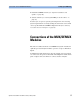
The device under test may have its own clock generator. The figure
below shows a setup example.
Figure 44 DUT Clock and Clock Data Recovery (CDR)
The clock from the DUT is fed into the MUX module. The clock output of
the MUX module is connected to the CLOCK/REF INPUT of the clock
module.
On the receiver side, the DEMUX module recovers the DUT clock pulse
and uses this as an external clock source for the analyzer system’s clock
module (CLOCK/REF INPUT).
16
/
43.2G Error
Detector Bundle
CDR
Divide
/
Divide
PLL
16
43.2G Pattern
Generator Bundle
DUT @
38 .. 43.2
Gb/s
593.75 .. 675 MHz
19 .. 21.6 GHz,
9.5 .. 10.8 GHz
9.5 .. 10.8 GHz,
2.375 .. 2.7 GHz
9.5 .. 10.8 GHz,
2.375 .. 2.7 GHz
593.75 .. 675 MHz