
Installation guide


Clock Connections Setting Up ParBERT 43G
Agilent 81250 ParBERT Installation Guide, February 2002 65
Both modules have clock input and output connectors. With ParBERT
43G, there are many ways for generating and connecting clock pulses.
Using the Built-in Clock Module
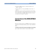
The simplest clock source is the E4808A clock module. Its use is
illustrated in the figure below.
Figure 43 Using the Built-in Clock Module
The clock module can use its own oscillator, or it can lock to an external
clock source. It has a clock multiplier and a clock divider that allow it to
use a variety of source frequencies. Its output is connected to the data
generator/analyzer modules and can also be connected to the MUX
module. Its output clock rate is limited to 675 MHz.
The MUX module has four clock output connectors that can provide four
subrates of the generated serial-line frequency: 1/2, 1/4, 1/16th, and
1/64th. If the serial-line frequency is set to 43.2 GHz, you can get clock
rates of 21.6 GHz, 10.8 GHz, 2.7 GHz, and 675 MHz.
NOTE 43 Gbit/s devices generally require clock frequencies of 2.7 GHz or a
multiple thereof. If the ParBERT shall source such a clock pulse, an
additional generator frontend is needed. This in turn requires an
additional data module and results in a configuration as shown in
Figure 42 on page 64.
16
/
Divide
PLL
43.2G Pattern
Generator Bundle
38 .. 43.2 Gb/s
593.75 .. 675 MHz (MCLK)
Internally or
externally:
9.5 .. 10.8 GHz,
or any subrate
:n, n = 1…255
Subrate clk out:
19.5 .. 21.6 GHz,
9.5 .. 10.8 GHz,
2.375 ..2.7 / 593.75 .. 675 MHz