
Installation guide


Modifying an Existing ParBERT System Setting Up ParBERT
Agilent 81250 ParBERT Installation Guide, February 2002 55
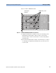
3 Plug the trigger input pod into the appropriate 16-pin socket on the
clock card, as indicated in Figure 36.
Figure 36 Clock Module Connections
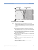
4 Reattach the side cover with the screws you removed earlier (see
Figure 25 on page 48 for the location of the screws), and reinsert the
clock module into the mainframe.
5 Re-connect all cables disconnected earlier.
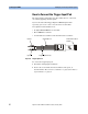
Call the Agilent support if you need additional probe leads. The required
part number is 16520-62102.
NOTE You need to remove the leads from the probe adapter header before
plugging them into the pod housing.
Socket for trigger
input pod