
Installation guide


Setting Up ParBERT Modifying an Existing ParBERT System
54 Agilent 81250 ParBERT Installation Guide, February 2002
How to Connect the Trigger Input Pod
The trigger input pod has eight sense lines which allow to control test
execution by applying external signals.
If you ordered the 8-line Trigger Input Pod E4805B Option #002
separately, you need to connect it to the master clock module.
Prerequisites for this installation are:
• An Agilent E4805B/E4808A clock module
• The ParBERT user software
• A 2-mm flathead screwdriver and a Torx T-10 size screwdriver
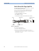
Figure 35 Trigger Input Pod
To connect the trigger input pod:
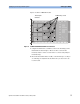
1 Shut down and unplug the mainframe.
2 Remove the clock module from the mainframe and open it, as
described under ”How to Remove a Module” on page 44 and ”How to
Open a Module” on page 47.
Connector to clock
module
Ground pins (2)
Trigger input lines (8)
Input 0
Input 7
S