
Installation guide


Modifying an Existing ParBERT System Setting Up ParBERT
Agilent 81250 ParBERT Installation Guide, February 2002 53
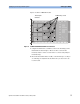
E4861B modules use different multi-pole connectors, as shown below:
Figure 34 Frontend Contacts of an E4861B Module
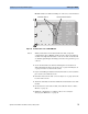
NOTE When you insert the new frontend, make sure that you press it
completely into place. Mind the position of the connectors and press
on them—it is important that these contacts are made. As the boards
are flexible, tightening the mounting screws does not guarantee good
contacts.
2 Secure the frontend to the main board using the screws that were
delivered with the frontend. See Figure 30 on page 50 and Figure 31
on page 51 for the locations of the screws.
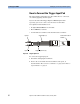
3 If you are installing an analyzer frontend, insert the receiver board into
place and secure it with its screws.
4 Remount and secure the side cover. See Figure 25 on page 48 for the
location of the screws.
5 Attach the label that was delivered with the frontend at the side of the
module.
6 Re-insert and reconnect the module, as described in ”How to Add a
Module” on page 44.
7 Finish the configuration according to ”How to Proceed After
Changing the Hardware” on page 56.
Frontend contacts
Receiver board contacts