
Installation guide


Modifying an Existing ParBERT System Setting Up ParBERT
Agilent 81250 ParBERT Installation Guide, February 2002 51
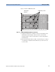
Figure 31 shows an E4861B module.
Figure 31 ParBERT E4861B Module With Cover Removed
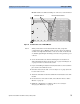
3 Using the Torx T-10 size screwdriver, remove the mounting screws
that hold the frontend in place. There are three screws for the
frontend, and two or three screws for the receiver board (analyzer
frontends only).
4 Lift off the frontend from the module, as shown in Figure 32. If you
are removing an analyzer frontend, make sure you also remove its
receiver board.
Two analyzer
frontends
Six Mounting screws