
Installation guide


Setting Up ParBERT Modifying an Existing ParBERT System
50 Agilent 81250 ParBERT Installation Guide, February 2002
Note also that the E4835A 675 MHz analyzer frontends are always
installed in pairs, where two frontends share a common receiver plug-in
board.
To exchange the frontends, you need the following:
• Either a generator frontend or an analyzer frontend
• The label delivered with the frontend
• A Torx T-10 size screwdriver (delivered with the mainframe)
Removing a Frontend
To remove a frontend:
1 Shut down the mainframe and remove the ParBERT module, as
described in ”How to Remove a Module” on page 44.
2 Using the Torx T-10 size screwdriver, remove the seven screws that
hold the side cover. See Figure 25 on page 48 for the location of the
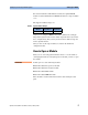
screws. An E4861A module will appear as shown in Figure 30.
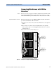
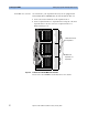
Figure 30 ParBERT E4861A Module With Cover Removed
Note the positions of the mounting screws.
Generator
frontend
Analyzer
frontend
Mounting screws