
Installation guide


Setting Up ParBERT Modifying an Existing ParBERT System
46 Agilent 81250 ParBERT Installation Guide, February 2002
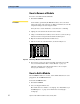
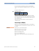
Figure 24 shows an example of the logical address switch.
Figure 24 Logical Address Switch
The coding is 8-bit binary. The example above refers to an address of 72,
which means 2
3
+ 2
6
or 01001000 in binary notation.
Table 4 shows the logical addresses to be used.
It is strongly recommended that you use the addresses listed in the table
above.
NOTE The embedded PC has a logical address of “0”.
7
LOGICAL ADDRESS
6543210
01
Table 4 Recommended Logical Addresses
Slot
Master
Mainframe
Expander
Mainframe 1
Expander
Mainframe 2
0 0 128 192
1 24 132 196
2 32 136 200
3 40 140 204
4 48 144 208
5 56 148 212
6 64 152 216
7 72 156 220
8 80 160 224
9 88 164 228
10 96 168 232
11 104 172 236
12 112 176 240