
Installation guide


Modifying an Existing ParBERT System Setting Up ParBERT
Agilent 81250 ParBERT Installation Guide, February 2002 45
3 Set the module’s logical address (LADDR).
See ”How to Set the Logical Addresses” on page 45 for instructions
and the recommended logical address.
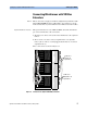
4 Insert the module into the mainframe.
Make sure that the central clock module is at the left-most position
and that all ParBERT modules are installed next to each other.
5 Using a 2-mm flathead screwdriver, secure the module to the
mainframe with the two retaining screws on top and bottom of the
front panel.
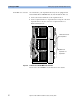
6 Connect the clock distribution cable from the module to its clock
module. Make sure that the clock distribution cables are properly
bundled.
See also ”Checking the Clock Distribution Cables” on page 32.
7 Finish up the changes as described under ”How to Proceed After
Changing the Hardware” on page 56.
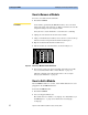
How to Set the Logical Addresses
Communication inside the system is coordinated by the modules’ logical
addresses. These are defined by setting DIP switches on each module.
NOTE Any time you rearrange the modules of a mainframe, you also have to
make sure that they have the correct logical addresses. Ignore the
address and ON/OFF information on the DIP switch—watch the
numbers printed on the module’s side cover.