
Installation guide


Setting Up ParBERT Setting Up a System with Expander Frames
40 Agilent 81250 ParBERT Installation Guide, February 2002
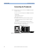
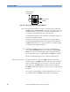
Figure 20 Master-Slave Connection of Clock Modules
NOTE The setup shown in Figure 19 refers to one single, fully synchronized
ParBERT system. The EXPANDER clock connectors of the master clock
module provide the clock reference for all three mainframes. There are
one master clock module and two slave clock modules.
A setup like this results in a system with three clockgroups and up to 33
data generator/analyzer modules.
If you do not connect the clock modules, then you set up an Agilent
81250 Parallel Bit Error Ratio Tester that comprises three independent
ParBERT systems. In this case, each system has one clockgroup and up
to 11 data generator/analyzer modules.
TIP Independent ParBERT systems can be frequency-synchronized by
connecting the TRIGGER OUT port of one system to the CLOCK/REF
INPUT port of the second system. This requires that the parameters of
the clock modules are set accordingly with the ParBERT user software.
Frequency-synchronization does not mean phase-synchronization.
IEEE 1394 link connections It is important that you connect the IEEE 1394 link modules of the
expander frames to the IEEE 1394 link module of the master mainframe.
It does not matter which ports you use. Do not connect the expander
frames directly to the IEEE 1394 PC to VXI card in the controller PC.
The IEEE 1394 link cables and clock reference cables are delivered with
the system.
You can now continue with the normal installation (there are no more
special instructions for ParBERT systems with expander frames).
OUT
OUT
OUT
IN
To slave clock
modules
Master clock to
master clock