
Installation guide


Setting Up a System with Expander Frames Setting Up ParBERT
Agilent 81250 ParBERT Installation Guide, February 2002 39
Connecting the Clock Reference and IEEE
1394 Links
NOTE This section describes the final connections for a standard multi-
mainframe configuration with the IEEE 1394 PC link to VXI interface. If
your installation has VXI bus extender modules, see also ”Connecting
Mainframes with VXI Bus Extenders” on page 41.
Now you have to make the final connections between the expander
frames and the master mainframe. These consist of the clock reference
cables and the IEEE 1394 link cable.
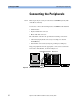
The connections between the mainframes are shown in Figure 19.
Figure 19 Clock Reference and IEEE 1394 Connections
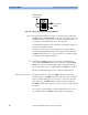
Clock module connections The IN port of the EXPANDER connectors of each mainframe is
connected to one of the OUT ports of the master mainframe. This means
that the master clock module is also connected to itself. These
connections are once more shown in Figure 20.
OUT
OUT
OUT
IN
IEEE 1394 link cable
IEEE 1394 link cable
To controller PC
OUT
OUT
OUT
IN
OUT
OUT
OUT
IN
From master mainframe
To expander frame 1
To expander frame 2
From master mainframe
IEEE 1394 link
connections
Clock reference
connections