
Installation guide


Getting Started ParBERT Overview
22 Agilent 81250 ParBERT Installation Guide, February 2002
If the hardware has been changed by adding or removing modules or
frontends, new virtual systems can be automatically created with the
Agilent 81250 Configuration Tool.
NOTE The user interface and remote control commands enable you to load and
operate any of the configured systems.
You can even operate several virtual systems in parallel by starting the
user interface more than once. Every user interface indicates the chosen
system in the bottom line of its main window.
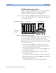
What Makes up a ParBERT System
If the Agilent 81250 Parallel Bit Error Ratio Tester has only one clock
module, then you have a system that comprises all data
generator/analyzer modules installed directly to the right of the clock
module, up to the next empty slot.
If the Agilent 81250 Parallel Bit Error Ratio Tester has two or three clock
modules connected in master-slave combination, then you have a system
that comprises more than one clockgroup. Each clockgroup includes all
modules that are located directly to the right of the clock module, up to
the next clock module or empty slot.
NOTE Only systems with expander frames (that means, more than 10 or 11 data
generator/analyzer modules are needed) require the clockgroups 2 and 3.
These clockgroups are automatically identified by the Agilent 81250
Configuration Tool.
If the Agilent 81250 Parallel Bit Error Ratio Tester has more than one
independent clock module—one that is not connected in master-slave
combination—then you have more than one independent systems. Each
system contains at least one clockgroup.
NOTE Independent systems are also automatically identified by the Agilent
81250 Configuration Tool. After starting the ParBERT user software, you
have to decide which system you wish to control.