
Installation guide


Getting Started ParBERT Overview
14 Agilent 81250 ParBERT Installation Guide, February 2002
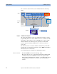
The central role of the firmware server is illustrated in the following
figure:
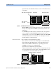
Figure 3 ParBERT Control Options
All clients of the firmware server—the graphical user interface and all
programming interfaces—use the firmware server to communicate with
the hardware. As the interfaces use the TCP/IP protocol, they can talk
with the firmware server directly (local operation) or via the LAN
(remote operation). Only the GPIB interface cannot be used from a
remote PC.
The firmware server accesses the hardware either directly via the VXI
bus (if it runs on an embedded controller) or via the IEEE 1394 PC link to
VXI (if it runs on an external PC).
So, two alternatives are available for controlling the system:
External controller • The E8491B IEEE 1394 PC link to VXI (opt. #013)
This option allows to use an external PC running under Windows NT
or Windows 2000 as the ParBERT controller. The option includes a
PCI board that is installed in the computer, a 1-slot VXI module which
is plugged into the mainframe, connection cable, and all required
software.
Graphical user
interface
GPIB
interface
SCPI command language
Socket – TCP/IP protocol
Parser
:
:
I/O driver
VISA library functions
Firmware
server
embedded VXI bus or IEEE 1394 PC link to VXI
embedded or
external
controller
LAN access
(from/to
other PC)
Module firmware
Hardware
VXI bus interface
VEE
pnp
C/C++
pnp
LabView
pnp
VB/VBA
pnp
Measurement
user interface
Clients
local or
remote PC