
Technical data

16 User’s and Service Guide Supplement
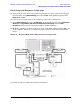
General Overview E8362B, E8363B and E8384B Option H85
Making High Power Measurements With Option H85
NOTE
Ratio measurements, such as gain, will be correctly displayed. However, the
displayed absolute power levels on the analyzer will not be correct. To
correctly interpret power levels and the gain of the booster amplifier, the
attenuator setting must be taken into consideration.
If no calibration has been performed or if the instrument is in an un-calibrated state, the
following must be taken into consideration when interpreting the measured data:
• The value of attenuation added to receiver A and B.
• The R channel reference level supplied from the coupler arm of the 20 dB coupler.
This procedure can be repeated to setup the reverse high power configuration.
CAUTION
The microwave PNA has over 20 frequency bands. During band-crossings, the
firmware turns off the RF power level. If you are testing a high-gain device
with an ALC when the PNA switches bands, the power shuts down and the
DUT ALC attempts to increase the gain. Microseconds later the PNA power
returns. However, in this short time frame the DUT or the VNA may be
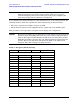
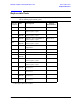
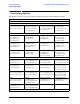
damaged. The band-crossings are listed in Table 2.
Table 2 Frequency Band-Crossing
Band Frequency (GHz) Band Frequency (GHz)
E8362/63/64B:
0 0 to 0.045 14 15.2 to 16.0
1 0.045 to 0.748 15 16.0 to 20.0
2 0.748 to 1.5 E8363/64B:
3 1.5 to 3.0 16 20.0 to 22.8
4 3.0 to 3.8 17 22.8 to 25.6
5 4.0 to 4.5 18 25.6 to 30.0
6 4.5 to 4.8 19 30.0 to 32.0
7 4.8 to 6.0 20 32.0 to 36.0
8 6.0 to 6.4 21 36.0 to 38.4
9 6.4 to 7.6 22 38.4 to 40
10 7.6 to 10.0 E8364B:
11 10.0 to 12.0 23 40.0 to 45.6
12 12.0 to 12.8 24 45.6 to 48.0
13 12.8 to 15.2 25 48.0 to 50.0