
Technical data


12 User’s and Service Guide Supplement
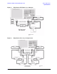
General Overview E8362B, E8363B and E8384B Option H85
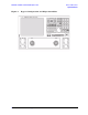
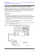
Making High Power Measurements With Option H85
Additional Setup
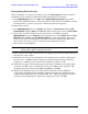
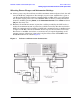
12. Turn off the booster amplifier.
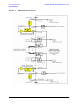
13. Connect the open port of the 20 dB coupler to the CPLR THRU connector on the front
panel for Port 1. This can also be done on Port 2 if reverse parameters high power
measurements are required.
14. Disconnect the REFERENCE SOURCE OUT and RCVR R1 IN jumper on the front
panel. Connect the coupled arm of the 20 dB coupler (along with any added
attenuation) to the RCVR R1 IN. The same instructions apply to Port 2 with one
exception; disconnect the jumper to RCVR R2 IN if high power measurements are
required for the reverse parameters.
15. Press [Menu/Dialog] then tab to Channel. In the pull down menu select Frequency
Offset and turn on the Frequency Offset Mode. In the Offset Setting set the Offset
to [0].
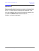
Figure 7 PNA Port 1 Amplifier, Coupler, Attenuator Connections