
Technical data


10 User’s and Service Guide Supplement
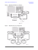
General Overview E8362B, E8363B and E8384B Option H85
Making High Power Measurements With Option H85
Making High Power Measurements With Option H85
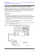
This section describes how to set up the analyzer to perform high power measurements.
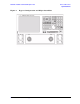
Analyzers equipped with the Option H85 can be configured to measure high power devices.
This ability is useful if the required power for the device under test is greater than the
analyzer can provide, or if the maximum output power from an amplifier under test
exceeds safe input limits for a standard analyzer.
Initial Setup
1. If the analyzer is in the bypass mode configuration remove the jumper between
SOURCE OUT and CPLR THRU connector on the front panel for Port 1. This can also
be done for Port 2 if high power measurements are necessary for the reverse parameters
of a device under test (DUT). Two booster amplifiers and two 20 dB couplers are
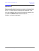
required for both forward and reverse measurements. Refer to Figure 1, “Maximum
Power Levels.”
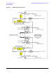
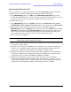
2. Connect the booster amplifier RF INPUT connector to the Port 1 SOURCE OUT
connector on the front panel of the analyzer.
3. Connect a 20 dB coupler (that operates within the frequency range of interest) to the
booster amplifier RF OUTPUT connector.
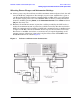
Figure 6 Booster Amplifier and 20 dB Coupler Connection Setup