
Technical data


8 User’s and Service Guide Supplement
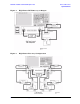
General Overview E8362B, E8363B and E8384B Option H85
Specifications
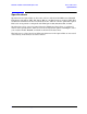
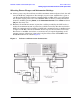
In the following diagrams a high power isolator or attenuator must be inserted at the Port
1 or Port 2 front panel jumper (CPLR THRU and SOURCE OUT ports) to protect the
internal solid state transfer switch (30 dB isolation recommended), or if reverse isolation of
the amplifier is less than 30 dB. Maximum power into the SOURCE OUT is 20 dBm.
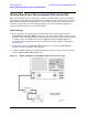
Optimum power level to all receivers is –12 dBm.
• Insert attenuators (A, B, R1 and R2 ports) to reduce power to receivers accordingly.
• Set the initial instrument state to –65 dBm test port power level to reduce the risk of
damage when powering on the unit.
• The recommended sweep mode is [STEP].
• Frequency Offset mode must be On and the R1 reference channel should be set to
External.
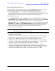
Figure 3 High Power One-way Input/Output