
Technical data

Agilent N516xA, N518xA, E8663B, E44x8C, and E82x7D Signal Generators Programming Guide 7
Creating and Downloading Waveform Files
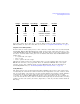
Understanding Waveform Data
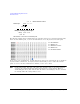
Notice that it takes only 15 bits (2
15
) to reach the Vmax (positive) or Vmin (negative) values. The
MSB determines the sign of the value. This is covered in “2’s Complement Data Format” on page 9.
Using E443xB ESG DAC Input Values
In this section, the words signal generator with or without a model number refer to an N5162A/82A
Agilent MXG, E4438C ESG, E8267D PSG. The signal generator input values differ from those of the
earlier E443xB ESG models. For the E443xB models, the input values are all positive (unsigned) and
the data is contained within 14 bits plus 2 bits for markers. This means that the E443xB DAC has a
smaller range:
• 0 = negative full scale output
• 8192 = 0 volts
• 16383 = positive full scale output
Although the signal generator uses signed input values, it accepts unsigned data created for the
E443xB and converts it to the proper DAC values. To download an E443xB files to the signal
generator, use the same command syntax as for the E443xB models. For more information on
downloading E443xB files, see “Downloading E443xB Signal Generator Files” on page 47.
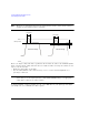
Scaling DAC Values
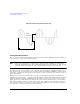
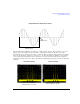
The signal generator uses an interpolation algorithm (sampling between the I/Q data points) when
reconstructing the waveform. For common waveforms, this interpolation can cause overshoot, which
may exceed the limits of the signal process path’s internal number representation, causing arithmatic
overload. This will be reported as either a data path overload error (N5162A/82A) or a DAC
over–range error condition (E4438C/E8267D). Because of the interpolation, the error condition can
occur even when all the I and Q values are within the DAC input range. To avoid the DAC over–range
problem, you must scale (reduce) the I and Q input values, so that any overshoot remains within the
DAC range.
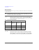
Voltage
DAC Range
Input Range
Binary Data
Hex Data
Vmax
Vmin
0 Volts
32767
–32768
0
01111111 11111111
00000000 00000000
00000000 00000001
11111111 11111111
10000000 00000000
1
-1
7FFF
0001
0000
FFFF
8000
0
32767
65535
32766
32768