Installation Guide Agilent Technologies E8257D/67D PSG Signal Generators This guide applies to the following signal generator models: E8257D PSG Analog Signal Generator E8267D PSG Vector Signal Generator Due to our continuing efforts to improve our products through firmware and hardware revisions, signal generator design and operation may vary from descriptions in this guide. We recommend that you use the latest revision of this guide to ensure you have up-to-date product information.
Notice The material in this document is provided “as is,” and is subject to change without notice in future editions. Further, to the maximum extent permitted by applicable law, Agilent disclaims all warranties, either express or implied with regard to this manual and to any of the Agilent products to which it pertains, including but not limited to the implied warranties of merchantability and fitness for a particular purpose.
Contents 1. Safety Information. . . . . . . . . . . . . . . . . . . . . . . . . . . . . . . . . . . . . . . . . . . . . . . . . . . . . . . . . . . . . . . 1 Instrument Markings. . . . . . . . . . . . . . . . . . . . . . . . . . . . . . . . . . . . . . . . . . . . . . . . . . . . . . . . . . . . . . .1 Warnings, Cautions, and Notes. . . . . . . . . . . . . . . . . . . . . . . . . . . . . . . . . . . . . . . . . . . . . . . . . . . . . . .2 General Safety Considerations . . . . . . . . . . . . . . . . . . .
Contents 4. Regulatory Information . . . . . . . . . . . . . . . . . . . . . . . . . . . . . . . . . . . . . . . . . . . . . . . . . . . . . . . . . . 33 Statement of Compliance . . . . . . . . . . . . . . . . . . . . . . . . . . . . . . . . . . . . . . . . . . . . . . . . . . . . . . . . . . 34 Assistance . . . . . . . . . . . . . . . . . . . . . . . . . . . . . . . . . . . . . . . . . . . . . . . . . . . . . . . . . . . . . . . . . . . . . . 34 Certification . . . . . . . . . . . . . . . . . . . . . . . .
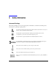
1 Safety Information Instrument Markings The following markings are used on the signal generator. Familiarize yourself with each marking and its meaning before operating the signal generator. The instruction manual symbol. The product is marked with this symbol when it is necessary for the user to refer to the instructions in the manual. The CE mark is a registered trademark of the European Community. If this symbol is accompanied by a year, it is the year when the design was proven.
Safety Information Warnings, Cautions, and Notes Warnings, Cautions, and Notes The following safety notations are used throughout this manual. Familiarize yourself with each notation and its meaning before operating the signal generator. WARNING Warning denotes a hazard. It calls attention to a condition or situation that could result in personal injury or loss of life. Do not proceed beyond a warning until the indicated conditions or situations are fully understood.
2 Getting Started 3
Getting Started Checking the Shipment Checking the Shipment 1. Inspect the shipping container for damage. Signs of damage may include a dented or torn shipping container or cushioning material that shows signs of unusual stress or compacting. 2. Carefully remove the contents from the shipping container and verify that your order is complete.
Getting Started Meeting Electrical and Environmental Requirements Meeting Electrical and Environmental Requirements Environment The signal generator is designed for use in the following environmental conditions: • indoor use • < 15,000 feet (4,572 meters) altitude • 0 to 55° C temperature, unless otherwise specified • 80% relative humidity (maximum) for temperatures up to 31° C, decreasing linearly to 50% relative humidity at 40° C CAUTION This product is designed for use in INSTALLATION CATEGORY
Getting Started Meeting Electrical and Environmental Requirements Line Settings The signal generator has an autoranging line voltage input.
Getting Started Meeting Electrical and Environmental Requirements AC Power Cord Localization The ac power cord included with the signal generator is appropriate to its geographic location. However, you can order additional ac power cords for use in different areas. The following table lists the available ac power cords, illustrates plug configurations, and identifies the geographic area in which each cord is appropriate.
Getting Started Configuring the Display Configuring the Display You can adjust the LCD display using features such as contrast, brightness, screen saver mode, and the screen saver delay. You can also toggle features such as inverse video, display updating in remote mode, and the screen saver on or off. Contrast and Brightness Press to decrease the display contrast.
Getting Started Configuring the Display input to the front panel. The display light turns on again when any front panel key is pressed or when a remote command is sent. The screen saver is set to off at the factory. Press Utility > Display > Screen Saver Mode. This toggles the screen saver mode between light-only mode and light-and-text mode. Adjust the screen saver mode to turn the light on, off, or to turn both the light and text on and off.
Getting Started Configuring for Remote Control Configuring for Remote Control GPIB Interface Configuration 1. Press Utility > GPIB/RS-232 LAN > GPIB Address. 2. Use the numeric keypad to set the desired address and press Enter. The arrow keys or the front panel knob can be used to set the desired address. The signal generator’s GPIB address is set to 19 at the factory. The acceptable range of addresses is 0 through 30.
Getting Started Configuring for Remote Control 6. Press IP Address and enter a desired address. Use the left and right arrow keys to move the cursor. Use the up and down arrow keys, front panel knob, or numeric keypad to enter an IP address. To erase the current IP address, press the Clear Text softkey. NOTE To remotely access the signal generator from a different LAN subnet, you must also enter the subnet mask and default gateway. See your system administrator to obtain the appropriate values. 7.
Getting Started Configuring for Remote Control RS-232 Interface Configuration 1. Press Utility > GPIB/RS-232 LAN > RS-232 Setup. 2. Press RS-232 Baud Rate. 3. Press the desired baud rate softkey. 4. Press RS-232 Echo Off On. This toggles the state of the SCPI echoing on the RS-232 connection. Set as desired. 5. Press Reset RS-232. This deletes the data from the RS-232 buffer, discarding any unprocessed SCPI input received over RS-232.
Getting Started Ordering Accessories Ordering Accessories The following accessories can be ordered when a signal generator is purchased, or at any time afterward. To order accessories, refer to “Contacting Agilent Sales and Service Offices” on page 16. Front Handles and Rack Mount Flanges Handles can be purchased and attached to the front of the signal generator. These handles can also be purchased with a rack mount kit to facilitate rack installation.
Getting Started Ordering Accessories Table 2-3 Available E8257D/67D PSG Documentation Document Type Description Part Number E8257D Data Sheet • • available options warranted specifications and typical performance 5989-0698EN E8267D Data Sheet • • available options warranted specifications and typical performance 5989-0697EN User’s Guide • • • • • description of features and functions signal generator operation tutorials optimization procedures concept information basic troubleshooting E8251-
Getting Started Proper Usage and Cleaning Proper Usage and Cleaning The signal generator cover protects against physical contact with internal assemblies that contain hazardous voltages, but does not protect against the entrance of water. To avoid damage and personal injury, ensure that liquid substances are positioned away from your signal generator. WARNING Personal injury may result if the signal generator is not used as specified. Unspecified use impairs the protection provided by the equipment.
Getting Started Contacting Agilent Sales and Service Offices Contacting Agilent Sales and Service Offices Assistance with test and measurements needs and information on finding a local Agilent office are available on the Internet at: http://www.agilent.com/find/assist You can also purchase E8257D/67D PSG accessories or documentation items on the Internet at: http://www.agilent.com/find/psg If you do not have access to the Internet, please contact your field engineer.
Getting Started Returning a Signal Generator to Agilent Technologies Returning a Signal Generator to Agilent Technologies To return your signal generator to Agilent Technologies for servicing, follow these steps: 1. Gather as much information as possible regarding the signal generator’s problem. 2. Call the phone number listed on the Internet (http://www.agilent.com/find/assist) that is specific to your geographic location. If you do not have access to the Internet, contact your Agilent field engineer.
Getting Started Returning a Signal Generator to Agilent Technologies 18 Chapter 2
3 Operation Verification Operation verification is a series of tests that, when completed, will either ensure that the signal generator is operating correctly, or will assist in pointing to the problem area. Operation verification does not ensure performance to specifications, but should provide a level of confidence that the signal generator is operating correctly within a minimum amount of time.
Operation Verification Performing a Self-Test Performing a Self-Test The self-test is a series of internal tests that checks different signal generator functions. If this test fails, refer to “Self-Test Failure” on page 21 for further instructions. Perform the following procedure to run a self-test: 1. Disconnect all external cables, including GPIB, LAN, and RS-232 cables. 2. Press Preset > Utility > Instrument Info/Help Mode > Self Test.
Operation Verification Performing a Self-Test Self-Test Failure If a self-test failure occurs, perform the following procedure: 1. Make sure all external cables, including GPIB, LAN, and RS-232 cables, are disconnected from the signal generator and perform the self-test again. 2. If the self-test continues to fail, send the signal generator to an Agilent service center for repair, with a detailed description of the failed test(s) and any other error messages that appeared on the display.
Operation Verification Checking the Maximum Leveled Power Checking the Maximum Leveled Power Perform the following procedure to check the maximum leveled power: 1. Press Preset. 2. Attach a 50Ω load to the RF OUTPUT. A power sensor, attenuator, or 50Ω termination is an example of a 50Ω load. 3. Press RF On/Off. The RF On annunciator is now displayed. 4. Press Mod On/Off. The Mod Off annunciator is now displayed. 5.
Operation Verification Checking the Maximum Leveled Power 3. Ensure that the RF OUTPUT connector is connected to a 50Ω load. 4. Ensure that the power level entered corresponds to the value listed in Table 3-1. 5. Refer to Table 3-2 for the recommended equipment and measure the output power. If the measured power level is more than the power level listed in Table 3-1, turn the front panel knob counterclockwise until the measured power level equals the power level in Table 3-1. 6.
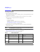
Operation Verification Checking the Maximum Leveled Power Table 3-1 Frequency and Power Level Limits Instrument Option Start Frequency Stop Frequency # Points E8257D Option 520 With Option 1E1 11 dBm 15 dBm 250 kHz 3.2 GHz 50 11 dBm 18 dBm 3.21 kHz 20 GHz 200 E8257D Option 540 With Option 1E1 7 dBm 14 dBm 250 kHz 3.2 GHz 50 7 dBm 16 dBm 3.21 kHz 20 GHz 200 7 dBm 12 dBm 20.1 GHz 40 GHz 200 3 dBm 13 dBm 250 kHz 3.2 GHz 50 3 dBm 14dBm 3.
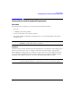
Operation Verification Checking the Output Power Checking the Output Power This test verifies the CW output power from the signal generator. If this test fails, refer to “Problems with Output Power” on page 32 for further instructions. Table 3-2 shows the recommended equipment for use with the E8257D signal generator when performing this test. Table 3-3 shows the recommended equipment for use with the E8267D signal generator when performing this test.
Operation Verification Checking the Output Power Table 3-2 Recommended Equipment for the E8257D E8257D Option 520 E8257D Option 540 E8257D Option 550 E8257D Option 567 ✔ Adapter, 3.5 (f) to (f) Agilent 1250-1749 APC 3.5 (f) to (f) adapter ✔ Adapter, 3.5 (f) to Type-N (m) Agilent 1250-1744 APC 3.5 (f) to Type-N (m) adapter Adapter, 1.85 mm (f) to V-Band Agilent V281A Coax 1.
Operation Verification Checking the Output Power Table 3-3 E8267D Option 520 Chapter 3 Recommended Equipment for the E8267D E8267D Option 532 E8667D Option 544 Test Equipment Recommended Agilent Test Equipment ✔ Adapter, APC 3.5 (f) to (f) Agilent 1250-1749 APC 3.5 (f) to (f) adapter ✔ Adapter, APC 3.5 (f) to Type-N (m) Agilent 1250-1744 APC 3.
Operation Verification Checking the Output Power Perform the following procedure to check the signal generator output power: 1. Zero and calibrate the power sensor to the power meter as shown: 2. Connect the equipment as shown: 3. Press Preset. 4. Press RF On/Off. The RF On annunciator is now displayed. 5. Press Mod On/Off. The Mod Off annunciator is now displayed. 6. Press Frequency and enter the first frequency value listed in Table 3-1. 7.
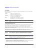
Operation Verification Checking the Output Power Table 3-4 Leveled Output Power Limits, E8257D E8257D Option 520 Frequency 250 kHz 3.2 GHz 20 GHz Option 540 Amplitude Limits Option dBm None 13 ±0.6 1EA 16 1E1 Frequency dB Limits Option dBm None 9 ±0.6 ±0.6 1EA 15 ±0.6 11 ±0.6 1E1 7 ±0.6 1E1 & 1EA 15 ±0.6 1E1 & 1EA 14 ±0.8 None 13 ±0.8 None 9 ±0.8 1EA 16 ±0.8 1EA 15 ±0.8 1E1 11 ±0.8 1E1 7 ±0.8 1E1 & 1EA 15 ±0.8 1E1 & 1EA 14 ±0.8 None 13 ±0.
Operation Verification Checking the Output Power Table 3-5 Leveled Output Power Limits, E8257D cont. E8257D Option 550 Frequency 250 kHz 3.2 GHz 20 GHz 40 GHz 50 GHz 30 Option 567 Amplitude Limits Option dBm dB None 9 ±0.6 1EA 15 1E1 Frequency Amplitude Limits Option dBm dB None 9 ±0.6 ±0.6 1EA 15 ±0.6 7 ±0.6 1E1 7 ±0.6 1E1 & 1EA 14 ±0.8 1E1 & 1EA 14 ±0.8 None 9 ±0.8 None 9 ±0.8 1EA 15 ±0.8 1EA 15 ±0.8 1E1 7 ±0.8 1E1 7 ±0.8 1E1 & 1EA 14 ±0.
Operation Verification Checking the Output Power Table 3-5 Leveled Output Power Limits, E8257D cont. Option 550 Frequency 60 GHz 67 GHz Option 567 Amplitude Limits Option dBm dB None 5 ±1.2 1EA 14 1E1 Frequency Amplitude Limits Option dBm dB None 5 ±1.2 ±1.2 1EA 14 ±1.2 3 ±1.2 1E1 3 ±1.2 1E1 & 1EA 10 ±1.2 1E1 & 1EA 10 ±1.2 None 5 ±1.2 None 5 ±1.2 1EA 12 ±1.2 1EA 12 ±1.2 1E1 3 ±1.2 1E1 3 ±1.2 1E1 & 1EA 10 ±1.2 1E1 & 1EA 10 ±1.
Operation Verification Checking the Output Power Problems with Output Power If a problem occurs when verifying output power levels, perform the following procedure: 1. Verify the power sensor being used in this test is the appropriate sensor. 2. Verify the power sensor calibration factors, if required, are correct. 3. Verify the power sensor is properly calibrated to the power meter. If the problem continues, perform a Power Level Accuracy performance test.
4 Regulatory Information 33
Regulatory Information Statement of Compliance Statement of Compliance This product has been designed and tested in accordance with IEC Publication 61010, Safety Requirements for Electronic Measuring Apparatus, and has been supplied in a safe condition. The instruction documentation contains information and warnings which must be followed by the user to ensure safe operation and to maintain the product in a safe condition.
Regulatory Information Compliance with Canadian EMC Requirements Compliance with Canadian EMC Requirements This is to declare that this ISM device complies with Canadian ICES-001. (Cet appareil ISM est conforme a la norme NMB du Canada.
Regulatory Information Compliance with Canadian EMC Requirements 36 Chapter 4
Index A I AC power cord, 6, 7 AC symbol, 1 accessories, 13 address, GPIB altitude requirements, 5 assistance, 34 Australian Communications Authority (C-tick) mark, 1 IEC Publication 61010, 34 instruction manual symbol, 1 inverse video adjustment, 8 IP address, setting, 10 ISM1-A symbol, 1 B kits, 13 brightness adjustment, 8 L C LAN configuration, 10 light adjustment, 9 Canadian EMC requirements, 35 Canadian Standards Association (CSA) mark, 1 CE mark, 1 cleaning, 15 configure display, 8 contrast a
Index troubleshooting maximum leveled power, 22 output power, 25 self-test, 20 V ventilation requirements, 5 verification, operation, 19 38 Index