Agilent Technologies E8257D/67D and E8663D PSG Signal Generators Installation Guide Agilent Technologies
Notices © Agilent Technologies, Inc. 2006-2009 Manual Warranty No part of this manual may be reproduced in any form or by any means (including electronic storage and retrieval or translation into a foreign language) without prior agreement and written consent from Agilent Technologies, Inc. as governed by United States and international copyright laws. The material contained in this manual is provided “as is,” and is subject to being changed, without notice, in future editions.
Contents 1. Safety Information. . . . . . . . . . . . . . . . . . . . . . . . . . . . . . . . . . . . . . . . . . . . . . . . . . . . . . . . . . . . . . . 1 Instrument Markings. . . . . . . . . . . . . . . . . . . . . . . . . . . . . . . . . . . . . . . . . . . . . . . . . . . . . . . . . . . . . . .1 Warnings, Cautions, and Notes . . . . . . . . . . . . . . . . . . . . . . . . . . . . . . . . . . . . . . . . . . . . . . . . . . . . . . .2 General Safety Considerations . . . . . . . . . . . . . . . . . . .
Contents 4. Regulatory Information . . . . . . . . . . . . . . . . . . . . . . . . . . . . . . . . . . . . . . . . . . . . . . . . . . . . . . . . . . 25 Statement of Compliance . . . . . . . . . . . . . . . . . . . . . . . . . . . . . . . . . . . . . . . . . . . . . . . . . . . . . . . . . . 25 Assistance . . . . . . . . . . . . . . . . . . . . . . . . . . . . . . . . . . . . . . . . . . . . . . . . . . . . . . . . . . . . . . . . . . . . . . 25 Certification . . . . . . . . . . . . . . . . . . . . . . . .
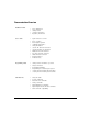
Documentation Overview Installation Guide User’s Guide Programming Guide SCPI Reference • • • • Safety Information • • • • • • • • • • • • Signal Generator Overview • • • • • • Getting Started with Remote Operation • • • • • • • Using this Guide Getting Started Operation Verification Regulatory Information Basic Operation Basic Digital Operation Optimizing Performance Analog Modulation Custom Arb Waveform Generator Custom Real Time I/Q Baseband Multitone Waveform Generator Two- Tone Waveform Ge
Service Guide Key Reference vi • • • • • Troubleshooting • Key function description Replaceable Parts Assembly Replacement Post- Repair Procedures Safety and Regulatory Information
1 Safety Information Instrument Markings The following markings are used on the signal generator. Familiarize yourself with each marking and its meaning before operating the signal generator. The instruction manual symbol. The product is marked with this symbol when it is necessary for the user to refer to the instructions in the manual. The CE mark is a registered trademark of the European Community. If this symbol is accompanied by a year, it is the year when the design was proven.
Safety Information Warnings, Cautions, and Notes This product complies with the WEEE Directive (2002/96/EC) marking requirements. The affixed label indicates that you must not discard this electrical/electronic product in domestic household waste. Product Category: With reference to the equipment types in the WEEE Directive Annex 1, this product is classed as a “Monitoring and Control instrumentation” product. Do not dispose in domestic household waste.
2 Getting Started Checking the Shipment 1. Inspect the shipping container for damage. Signs of damage may include a dented or torn shipping container or cushioning material that shows signs of unusual stress or compacting. 2. Carefully remove the contents from the shipping container and verify that your order is complete. The following items are shipped standard with each instrument: • installation guide • documentation CD- ROM CD- ROM contents are also available in hard copy format.
Getting Started Preliminary Meeting Electrical and Environmental Requirements Preliminary Meeting Electrical and Environmental Requirements Environment The signal generator is designed for use in the following environmental conditions: • indoor use • <15,000 feet (4,572 meters) altitude • 0 to 55° C temperature, unless otherwise specified • 80% relative humidity (maximum) for temperatures up to 31° C, decreasing linearly to 50% relative humidity at 40° C CAUTION This product is designed for use in INSTALL
Prelimniary Getting Started Preliminary Configuring the Display Connecting the AC Power Cord This is a Safety Class 1 Product provided with a protective earth ground incorporated into the power cord. The front panel switch is only a standby switch; it is not a line switch. The AC power cord is the disconnecting device that disconnects the signal generator mains circuits from the mains supply.
Getting Started Preliminary Configuring the Display Preliminary Inverse Video Press Utility > Display > Inverse Video Off On. This toggles between inverse video mode and normal display mode. The normal display mode for the signal generator is dark text on a light background. Inverse video mode is light text on a dark background. Inverse video is a persistent state; it is not affected by a signal generator preset or power cycle. Screen Saver Press Utility > Display > Screen Saver Off On.
Prelimniary Getting Started Preliminary Configuring for Remote Control Configuring for Remote Control GPIB Interface Configuration 1. Press Utility > GPIB/RS-232 LAN > GPIB Address. 2. Use the numeric keypad to set the desired address and press Enter. The arrow keys or the front panel knob can be used to set the desired address. The signal generator’s GPIB address is set to 19 at the factory. The acceptable range of addresses is 0 through 30.
Getting Started Preliminary Configuring for Remote Control Preliminary DHCP Configuration 1. Press Utility > GPIB/RS-232 LAN > LAN Setup. NOTE If the DHCP server uses dynamic DNS to link the hostname with the assigned IP address, the hostname may be used in place of the IP address. Otherwise, the hostname is not usable and you may skip steps 2 through 4. 2. Press Hostname. NOTE Hostname field will only be available when the DHCP is off (Manual mode). 3.
Prelimniary Getting Started Preliminary Ordering Accessories Ordering Accessories The following accessories can be ordered when a signal generator is purchased, or at any time afterward. To order accessories, refer to “Contacting Agilent Sales and Service Offices” on page 11. Front Handles and Rack Mount Flanges Handles can be purchased and attached to the front of the signal generator. These handles can also be purchased with a rack mount kit to facilitate rack installation.
Getting Started Preliminary Proper Usage and Cleaning Preliminary Table 2-3 Available E8257D/67D and E8663D PSG Documentation Document Type Description Part Number User’s Guide • • • • • description of features and functions signal generator operation tutorials optimization procedures concept information basic troubleshooting E8251- 90353 Key Reference • softkey and hardkey descriptions E8251- 90354 Programming Guide • • • remote operation procedures programming examples downloading and using
Prelimniary Getting Started Preliminary Contacting Agilent Sales and Service Offices Contacting Agilent Sales and Service Offices Assistance with test and measurements needs and information on finding a local Agilent office are available on the Internet at: http://www.agilent.com/find/assist You can also purchase E8257D/67D or E8663D PSG accessories or documentation items on the Internet at: http://www.agilent.com/find/psg If you do not have access to the Internet, please contact your field engineer.
Getting Started Preliminary Returning a Signal Generator to Agilent Technologies Preliminary 12 Chapter 2
3 Operation Verification NOTE For the instrument to meet performance specifications allow a warm up period of 45 minutes within an operational temperature range of 0 to 55 °C. For more information, refer to the PSG signal generator Data Sheet. Operation verification is a series of tests that, when completed, will either ensure that the signal generator is operating correctly, or will assist in pointing to the problem area.
Operation Verification Checking the Maximum Leveled Power • The current status of the self-test is: Incomplete. Not all tests have been run. When the self- test is complete, one of the following messages will be displayed: • The current status of the self-test is: Passed • The current status of the self-test is: Failure. One or more tests have failed.
Operation Verification Checking the Maximum Leveled Power 10. Press Return > Sweep > Freq. The SWEEP annunciator is now on and a continuous sweep will begin. During the sweep, the progress bar becomes active on the display, indicating the status of the current sweep. 11. Watch the display and ensure that the Unlevel annunciator does not appear at any time during a full sweep. The Unlevel annunciator may turn on and off, or remain on; both conditions indicate a failure.
Operation Verification Checking the Maximum Leveled Power Table 3-1 Frequency and Power Level Limits (For PSGs with s/n prefixes
Operation Verification Checking the Maximum Leveled Power Table 3-2 Frequency and Power Level Limits (For PSGs with s/n prefixes >=US4928/MY4928) Amplitude Instrument Model E8257D Option 520 E8257D Option 521 E8257D Option 532 E8257D Option 540 E8257D Option 550 and Option 567 E8267D Option 520 E8267D Option 532 and Option 544 E8663D Frequency # Points Standard Option 1EU Option 1E1 Options 1EU and 1E1 Start Stop 15 dBm 24 dBm 13 dBm 24 dBm 250.1 kHza 3.
Operation Verification Checking the Output Power Maximum Leveled Power Check Failure If a maximum leveled power check fails, perform the following procedure: 1. Verify the limits for that particular option using the data sheet. 2. If the Unlocked annunciator is displayed, refer to the Troubleshooting chapter of the E8257D/67D PSG Signal Generators Service Guide. 3. Ensure that the RF OUTPUT connector is connected to a 50Ω load. 4.
Operation Verification Checking the Output Power Table 3-3 Recommended Equipment for the E8257D E8257D Option 520 E8257D Option 521 ✔ E8257D Option 532 E8257D Option 540 E8257D Option 550 ✔ ✔ ✔ E8257D Option 567 ✔ ✔ ✔ ✔ ✔ ✔ ✔ ✔ Test Equipment Recommended Agilent Test Equipment Power Sensor, Input: 2.
Operation Verification Checking the Output Power Table 3-4 Recommended Equipment for the E8267D E8267D Option 520 E8267D Option 532 E8667D Option 544 ✔ ✔ ✔ Test Equipment Recommended Agilent Test Equipment Power Sensor, Input: Type- N (m) Agilent E9304A E- Series power sensor or Agilent 8482A power sensor Power Sensor, Input: APC 3.5 (m) Agilent E4413A E- Series power sensor ✔ Power Sensor, Input: 2.
Operation Verification Checking the Output Power 2. Connect the equipment as shown: 3. Press Preset. 4. Press RF On/Off. The RF On annunciator is now displayed. 5. Press Mod On/Off. The Mod Off annunciator is now displayed. 6. Press Frequency and enter the first frequency value listed for your instrument model in Table 0- 5. NOTE Some typical option configurations and their maximum output power limits are shown in Table 0- 5.
Operation Verification Checking the Output Power Table 3-5 Frequency and Power Level Limits (For PSGs with s/n prefixes
Operation Verification Checking the Output Power Table 3-6 Frequency and Power Level Limits (For PSGs with s/n prefixes >US4928/MY4928) Frequency Instrument Model E8257D Option 520 E8257D Option 521 E8257D Option 540 E8257D Option 550 E8257D Option 567 E8267D Option 520 Chapter 3 Amplitude / Limits Standard Option 1EA Option 1E1 Options 1EA and 1E1 250 kHz 13 dBm / ±0.6 16 dBm / ±0.6 11 dBm / ±0.6 15 dBm / ±0.6 3.2 GHz 13 dBm / ±0.8 16 dBm / ±0.8 11 dBm / ±0.8 15 dBm / ±0.
Operation Verification Checking the Output Power Table 3-6 Frequency and Power Level Limits (For PSGs with s/n prefixes >US4928/MY4928) Frequency Instrument Model E8267D Option 532 and Option 544 NOTE Amplitude / Limits Standard Option 1EA Option 1E1 Options 1EA and 1E1 250 kHz 12 dBm / ±1.0 N/A N/A N/A 3.2 GHz 12 dBm / ±1.0 N/A N/A N/A 20 GHz 14 dBm / ±1.0 N/A N/A N/A 40 GHz 12 dBm / ±1.0 N/A N/A N/A 44 GHz 10 dBm / ±0.
4 Regulatory Information Statement of Compliance This product has been designed and tested in accordance with IEC Publication 61010, Safety Requirements for Electronic Measuring Apparatus, and has been supplied in a safe condition. The instruction documentation contains information and warnings which must be followed by the user to ensure safe operation and to maintain the product in a safe condition.
Regulatory Information Declaration of Conformity Declaration of Conformity A copy of the Manufacturer’s EU Declaration of Conformity for this instrument can be obtained by contacting your local Agilent Technologies sale representative. (Refer to “Contacting Agilent Sales and Service Offices” on page 11.
Index A AC power cord 5 AC symbol 1 accessories 9 address, GPIB altitude requirements 4 assistance 25 Australian Communications Authority (C-tick) mark 1 B brightness adjustment 5 C Canadian EMC requirements 25 Canadian Standards Association (CSA) mark 1 CE mark 1 cleaning 10 configure display 5 contrast adjustment 5 CSA mark 1 C-tick mark 1 D declaration of conformity 26 DHCP configuration 8 display adjustments 5, 6 documentation 9 documentation, list of v E electrical requirements 4 environmental requ
Index T temperature requirements 4 troubleshooting maximum leveled power 14 output power 18 self-test 13 V ventilation requirements 4 verification, operation 13 28 Index