
Technical data
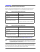
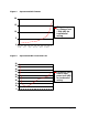

8 User’s and Service Guide Supplement
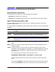
Upconverter Mixer
The following procedure will aid in determining if the upconverter mixer is functional:
CAUTION
Possible damage may occur if RF upconverter input levels exceed 20 dBm or if
reverse power is applied at the RF output connector. First verify all cable
configurations are correct before applying a signal to the instrument.
The RF step attenuator cable to the coax switch is functional if the instrument
operates as a standard synthesizer.
The RF cable from the coupler output is also functional if the instrument
operates as a standard synthesizer.
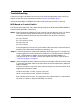
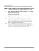
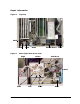
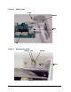
Step 1. Verify that the RF cable is connected from the connector labeled RF upconverter
on the rear panel to the mixer’s IF input port. Verify the power at the connection
to the mixer with RF Source applied.
Step 2. Verify the power through the cables to LO Input of the mixer (bottom
connector). The power should be close to the power level coming from the
Coupler Output. Replace the cables if power insertion loss is excessive and
damage is suspected. These cables have a K-type connector and a 2.92 mm
adapter should be used for mating to connectors.
Step 3. If all of the cables have been verified and are functional, verify the mixer
orientation with the markings on the outside of the mixer LO down, RF
Connector up and IF Connector facing rear of instrument. Replace the mixer
and verify its functionality by following the verification procedure.