
Technical data

User’s and Service Guide Supplement 7
Troubleshooting
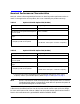
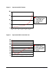
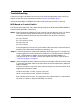
If there is no signal a problem has occurred. First check the equipment setup, verifying
outputs on the sources and connections. Refer to Figure 4 through Figure 7 .
Verify that the E8247C and E8257C/D Option H30 Upconverter switch is working:
MID Board or Coaxial Switch
The following procedure will aid in determining whether the MID board (E8251-60089) or
the coax switch (87222E) is functional.
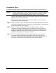
Step 1. Select upconverter mode on/off, then listen for the coax switch to click. If it doesn’t
click, check the ribbon cable connection to the switch (under switch/mixer
assembly). Remove the switch end of the cable from the switch and verify:
pin 1 for +32 Vdc,
pin 7 for +5 Vdc or 0 Vdc
pin 8 for +5.2 Vdc
pin 9 for Ground
If the voltages are incorrect, verify the ribbon cable connection to the MID board
assembly. The ribbon cable should be connected to J14.
Step 2. Cycle the upconverter mode on/off repeatedly while looking at pin 7 voltage. Pin 7
should toggle from +5 Vdc (upconverter mode on) to 0 Vdc (upconverter mode off).
If pin 7 voltage does not toggle, either the MID board (E8251-60089) or a
configuration error is at fault. Consult with Agilent Service for repair. Refer to
“Contacting Agilent” on page 17.
Step 3. If the voltages and control signal are present at the ribbon cable as verified in step
1, reconnect the ribbon cable to the coax switch and select upconverter mode and
toggle it ON/OFF.
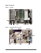
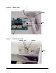
To verify the switch is not ultra quiet, measure the ports on the coax switch while
toggling the upconverter mode.
(Coupler out) PORT 1 PORT 2 (mixer LO input)
(Atten. input) PORT 4 PORT 3 (mixer RF output)
Port 4 should connect to port 3 in upconverter On mode and port 1 in upconverter
Off mode. If it doesn’t, replace the 87222E coax switch.