
Technical data

User’s and Service Guide Supplement 3
Nominal Performance Characteristics
Nominal values indicate expected performance or describe product performance that is
useful in the application of the product, but is not covered by the product warranty.
NOTE
When in upconverter mode, the displayed RF output power level is LO drive.
The displayed RF power in upconverter mode does not represent the power of
the upconverted signal at the RF output.
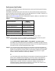
The maximum RF power output of the E8247C and E825C Option H30 is reduced by
2 dBm due to the added insertion loss of the coax transfer switch required for the design.
For units with Option H30, subtract 2 dBm from the power output specifications listed in
Table 1 of the standard user’s guides E8251-90253 and E8251-90353.
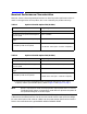
Table 1 Option H30 with Option 520 (20 GHz)
Description Frequency
Rear panel frequency range 100 kHz to 6 GHz
Conversion loss for upconverted signal to
the front panel
–10 to –15 dBm
Front panel RF upconverted frequency
range
200 kHz to 26 GHz
Usable IF Bandwidth (dependent on the
IF frequency used on rear panel)
< 2 dB over 1 GHz span ≤ 3 GHz IF Frequency
< 20 dB over 1 GHz span > 3 GHz IF Frequency
Table 2 Option H30 with Option 540 (40 GHz)
Description Frequency
Rear panel frequency range 100 kHz to 6 GHz
Conversion loss for upconverted signal to
the front panel
–10 dB (6 GHz) to –28 dB (46 GHz)
Front panel RF upconverted frequency
range
6 to 46 GHz
Usable IF Bandwidth (depends on the
IF frequency used on rear panel)
1
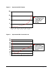
1. Conversion loss and IF bandwidth flatness will degrade contingent on the IF Input
frequency and the upconverted frequency. Refer to Figure 1 and Figure 2 on page 4.
< 2 dB over 1 GHz span ≤ 3 GHz IF Frequency
< 20 dB over 1 GHz span > 3 GHz IF Frequency