Agilent E8247C/E8257C PSG CW and Analog Signal Generators Self Guided Demo Product Note
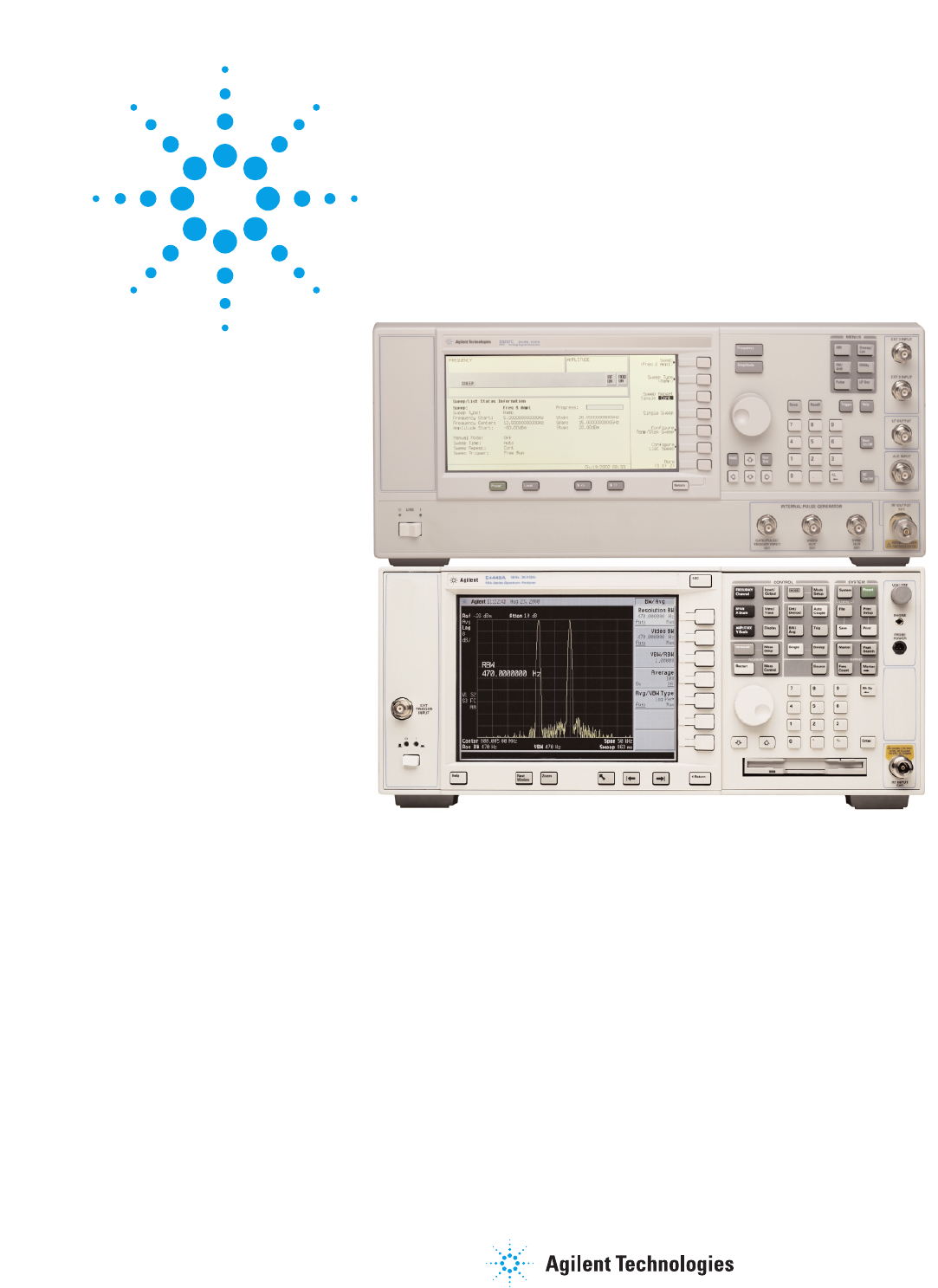
Agilent E8247C 250 kHz - 40 GHz PSG CW signal generator Agilent E8257C 250 kHz - 40 GHz PSG analog signal generator 2
Table of Contents Part 1: Configuring the RF Output 2 Part 2: Configuring Analog Modulation (E8257C Only) 20 Part 3: Configuring the LF Output (E8257C Only) 22 Part 4: Using Data Storage Functions 25 Part 5: Using Table Editors 30 Part 6: Configuring for Remote Control 31 Conventions used in this demonstration In this self guided demonstration hard keys on the instrument front panel are shown as [Hard Keys]. The soft keys at the right of the display are shown as {Soft Keys}.
Part 1: Configuring the RF Output This section explains how to create continuous wave and swept RF outputs. Configuring a continuous wave RF output Using these procedures, you will learn how to set the following parameters: • RF output frequency • frequency reference and frequency offset • RF output amplitude • amplitude reference and amplitude offset Setting the RF output frequency Instruction 1. Press [Preset]. Note This returns the signal generator to the factory-defined instrument state.
Setting the frequency reference and frequency offset The following procedure sets the RF output frequency as a reference frequency to which all other frequency parameters are relative. The frequency initially shown on the display will be 0.00 Hz (the frequency output by the hardware minus the reference frequency). Although the display changes, the frequency output does not change. Any subsequent frequency changes are shown as incremental or decremental to 0 Hz.
Setting the amplitude reference and amplitude offset The following procedure sets the RF output power as an amplitude reference to which all other amplitude parameters are relative. The amplitude initially shown on the display will be 0 dB (the power output by the hardware minus the reference power). Although the display changes, the output power does not change. Any subsequent power changes are shown as incremental or decremental to 0 dB. 6 Instruction 1. Press [Preset]. Note 2.
Configuring a swept RF output NOTE The signal generator has two sweep types: step and list. Step sweep data cannot be saved to the instrument state register or to the memory catalog. Step sweep configurations are reset at preset or when the signal generator’s line power is cycled. Following an explanation of the differences between step sweep and list sweep, you will learn two ways to configure the signal generator’s RF output to sweep a defined set of frequency, amplitude, and dwell time points.
Configuring and activating a single step sweep In this procedure, you will create a step sweep with nine, equally spaced points and the following parameters: Instruction 1. Press [Preset]. Note 2. Press [Sweep/List]. This opens a menu of sweep softkeys. 3. Press {Sweep Repeat Single Cont}. This toggles the sweep repeat from continuous to single. 4. Press {Configure Step Sweep}. • frequency range from 500 MHz to 600 MHz 5. Press {Freq Start} > [500] > {MHz}.
Activating continuous step sweep Instruction Press {Sweep Repeat Single Cont}. Note This toggles the sweep from single to continuous. The SWEEP annunciator is activated indicating that the signal generator is sweeping. The progression of the sweep is displayed by a progress bar. A continuous repetition of the frequencies and amplitudes configured in the step sweep are now available at the RF OUTPUT connector. Configuring a list sweep using step sweep data Instruction 1. Press {Sweep Repeat Single Cont}.
Instruction 7. Highlight the frequency item for point 8, then press {Insert Item}. Note NOTE During this process, several error messages are generated to inform you that the frequency and power (or power and dwell) lists are of unequal size. You will correct this problem in the following steps, however the ERR annunciator does not turn off until you clear the error queue. To clear the error queue and return to the List Mode Values table editor, follow these steps. a.
Part 2: Configuring Analog Modulation (E8257C Only) The 8257C can modulate the RF carrier with four types of analog modulation: amplitude, frequency, phase, and pulse. AM, FM, and ΦM Sources • AM, FM, and ΦM have two source paths each. These multiple source paths are summed internally for composite modulation of the RF output. • Each path can be fed by one of four sources: Internal 1, Internal 2, External 1 or External 2. • Only one path can be active for each source.
Configuring AM Figure 1: AM Using this procedure, you will learn how to create a multipath amplitude-modulated RF carrier with the following characteristics: • RF output frequency set to 4 GHz • RF output amplitude set to 0 dBm • AM Path 1 depth set to 90 percent • AM Path 1 rate set to 10 kHz • AM Path 1 waveform set to sine • AM Path 2 depth set to 40 percent • AM Path 2 waveform set to triangle • AM Path 2 rate set to 5 kHz Setting the RF output frequency Instruction 1.
Creating a multipath AM configuration Use these steps to configure a multipath AM configuration. AM Path 1 and AM Path 2 are summed internally for composite modulation. Either path can be switched to any one of the modulation sources (internal 1 or 2, external 1 or 2), though any given source can only be routed to one modulation type. Instruction 1. Press {AM Path 1 2} to toggle to AM Path 2. Note This opens a menu of softkeys where you can define a second unique amplitude modulation configuration. 2.
Figure 2: Multipath AM Viewing the signal on an Agilent E4440A PSA spectrum analyzer Instruction 1. Press [Preset]. Note 2. Press [Frequency] > [4] > {GHz}. The Center FREQUENCY area of the display now reads 4.000 000 00 GHz. 3. [Press Span] > [40] > {kHz}. The Span are of the display now reads 40 kHz.
Figure 3: FM Activating FM The signal generator is now configured to output a 0 dBm, frequencymodulated carrier at 4 GHz with the FM deviation set to 75 kHz and the FM rate set to 10 kHz. The shape of the waveform is a sinewave. (Notice that sine is the default for the FM Waveform softkey. Press More (1 of 2) to see the softkey.) Follow these remaining steps to output the frequency-modulated signal. Viewing the signal on an Agilent E4440A PSA spectrum analyzer Instruction 1. Press [FM Off On].
Configuring ΦM Figure 4: ΦM Using this procedure, you will learn how to create a phase-modulated RF carrier with the following characteristics: • RF output frequency set to 4.0 GHz • RF output amplitude set to 0 dBm •ΦM deviation set to 0.25 l radians • ΦM rate set to 30 kHz Setting the RF output frequency Instruction 1. Press [Preset]. Note 2. Press [frequency] > [4] > {GHz}. The FREQUENCY area of the display now reads 4.000 000 000 00 GHz. Setting the RF output amplitude Instruction 1.
Configuring pulse modulation Figure 5: Pulse Modulation Using the following procedure you will learn how to create a pulsemodulated RF carrier with the following characteristics: • RF output frequency set to 4 GHz • RF output amplitude set to 0 dBm • pulse period set to 100.0 µsec • pulse width set to 24.0 µsec • pulse source set to internal free-run Instruction 1. Press [Preset]. Note 2. Press [frequency] > [4] > {GHz}. The FREQUENCY area of the display now reads 4.000 000 000 00 GHz.
Part 3: Configuring the LF Output (E8257C Only) The E8257C has a low frequency (LF) output. The LF output’s source can be switched between an internal modulation source (internal monitor 1 or 2) or an internal function generator (function generator 1 or 2). Using internal monitor 1 or 2 as the LF output source, the LF output provides a replica of the signal from either internal source (1 or 2) that is being used to modulate the RF output.
Configuring the LF output with an internal modulation source In this example, the internal FM modulation is the LF output source. Configuring the internal modulation as the LF output source Instruction 1. Press [Preset]. Note 2. Press the [FM/ΦM] hardkey. Configuring the Low frequency output 3. Press {FM Dev} > [75] > {kHz}. This sets the FM deviation to 75 kHz. 4. Press {FM Rate} > [10] > {kHz}. This sets the FM rate to 10 kHz. 5. Press {FM Off On}.
Part 4: Using Data Storage Functions This section explains how to use the two forms of signal generator data storage, the memory catalog, and the instrument state register. Using the memory catalog The signal generator’s interface for stored files is the memory catalog. From there you can view, copy, rename, and delete files, either from the signal generator’s front panel or via remote controller. (For information on performing these tasks remotely, see the programming guide.
Viewing stored files Instruction 1. Press [Utility] > {Memory Catalog} > {Catalog Type}. Note The default catalog type is All (all files in the memory catalog are listed in alphabetical order, regardless of type). When viewing all files, file name listings include a pointer to their file type, such as @STATE or @LIST. 2. Press [List]. The Catalog of List Files is displayed. 3. Press {Catalog Type} > {State} The Catalog of State Files is displayed. 4.
Using the instrument state register The instrument state register is a section of memory divided into 10 sequences (numbered 0 through 9), each containing 100 registers (numbered 00 through 99). It is used to store and recall frequency, amplitude, and E8257C, modulation settings. It provides a quick alternative to reconfiguring the signal generator via the front panel or SCPI commands when switching between different signal configurations.
Saving an instrument state Instruction 1. Press [Preset]. Using this procedure, you will learn how to save current instrument settings to the instrument state register. 2. Configure the signal generator with the following settings: Note a. Press [Frequency] > [800] > {MHz}. b. Press [Amplitude] > [0] > {dBm}. c. Press [AM] > {AM Off On}. This enables amplitude modulation (AM annunciator is on). 3. Press [Save] > {Select Seq}. The sequence number becomes the active function.
Deleting registers and sequences Using this procedure, you will learn how to delete registers and sequences saved to an instrument state register. To delete a specific register within a sequence Instruction 1. Press [Preset]. Note 2. Press the [Recall] or [Save] hardkey. Notice that the {Select Seq} softkey shows the last sequence that you used. 3. Press {Select Seq} and enter the sequence number containing the register you want to delete. To delete all registers within a sequence 4.
Part 5: Using Table Editors The PSG signal generator uses table editors to simplify configuration tasks such as creating a list sweep. Table Items values arraigned in numbered rows and titled columns Delete Item deletes the item from the bottom row of the currently selected column Using the List Mode Values table editor, the following section familiarizes you with basic table editor functionality.
Part 6: Configuring for Remote Control This section will show you how to configure the signal generator to interface with a remote controller. Follow the instructions in the appropriate section to configure your PSG signal generator for remote control. NOTE For a complete system interface required equipment list and installation procedure, see the programming guide. Configuring for a parallel GPIB (IEEE 488.2, 1987) interface Selecting a GPIB Address Instruction Note 1.
Configuring for a serial (RS-232) auxiliary interface Instruction 1. Press [Utility] > {GPIB/RS-232 LAN} > {RS-232 Setup}. Note 2. Press {RS-232 Baud Rate}. Press the desired baud rate softkey to set the baud rate. 3. Press {RS-232 Echo Off On}. This toggles the state of the SCPI echoing on the RS-232 connection. Set as desired. 4. Press {Trans/Recv Pace None Xon}.
Agilent Technologies’ Test and Measurement Support, Services, and Assistance To find out more visit: www.agilent.com/find/psg Related Agilent literature PSG Signal Generator Brochure Literature number 5988-7538EN Agilent E8247/E8257C PSG CW and Analog Signal Generator Data Sheet Literature number 5988-2412EN Warranty The standard warranty is three years. An extended five-year warranty is available with Option W50.