
Technical data


Chapter 3 75
1xEV-DO Analyzer and Over Air Test
Interpreting the Display
1xEV-DO Analyzer and Over Air
Test
Interpreting the Display
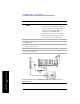
The 1xEV-DO Tx screen is divided into two sections, and the 1xEV-DO Over Air
screen is divided into three sections. The extra, third section in the 1xEV-DO Over
Air screen shows the OTA PN Scanner results, and appears at the top of the display.
You can switch the OTA PN Scanner
On or Off independently in either a 1xEV-DO
Tx Analyzer measurement or in a 1xEV-DO Over Air measurement. The presence
or absence of the OTA PN Scanner is the main difference between the 1xEV-DO Tx
Analyzer screen and the 1xEV-DO Over Air screen.
If you have the OTA PN Scanner display switched
On, it appears at the top of the
screen. The code domain trace display in the center. The pilot dominance and
multipath power parameters are shown to the left of the screen. When you are
making Over the Air measurements, awareness of these two parameter values helps
you be sure that you are making valid measurements on the sector of interest.
The code domain trace display contains 128 Walsh codes when CDP Type is
MAC 128, or 64 Walsh codes when CDP Type is MAC 64. These are shown in a
bit-reversed order to represent the combined code channels for the varying data rate
traffic channels. The Y-axis labels display the relative power (dB) or absolute power
(dBm), threshold level, and dB/division. The X-axis labels display active channel
Walsh Code numbers. Active code channels shown on the display include:
• Active MAC (Medium Access Control) RPC (Reverse Power Control) channels
(shown in orange)
• RA (Reverse Activity) MAC channel (shown in light blue)
• Noise (shown in light gray)
• Unknown (MAC indexes 0 to 3 only) (typically these are displayed in gray, that
is, as noise. If they are found to be active, they are shown in light brown)
• Pilot (shown as a red bar, and only when CDP Type is Pilot)
The metrics display shows 14 measurement parameters displayed below the CDP
display in three columns and five rows—each with a value and units. For more
information about the parameters in the metric display, refer to “Metrics Provided
by the 1xEV-DO Tx and Over Air Analyzer Measurement” on page 104.
The time reference indicator is at the bottom right. For each indicator the text
indicates which time reference you have chosen. A green LED indicates a locked
condition, a red “X” indicates an unlocked condition. You must have a valid time
references (either from the GPS system, or from an Even Second Clock) to make