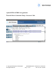
Agilent E6701A GPRS Lab Application Tutorial: Direct Connection Using a Crossover Cable Copyright 2002 Agilent Technologies. All Rights Reserved. 10001809-E6701A Tutorial Direct Connection Page 1 of 30 Rev. 1.0; Feb.
Table of Contents Table of Contents .......................................................................................................................... 2 About This Tutorial ...................................................................................................................... 4 Introduction ................................................................................................................................... 4 Equipment Required for this Tutorial ..........................
Appendix A: Installing a WAP Gateway into a PC ................................................................ 25 Infinite WAPLite Gateway (by Captaris Inc.) ...................................................................................25 Appendix B: Troubleshooting................................................................................................... 26 Appendix C. Glossary ................................................................................................................
About This Tutorial This tutorial gives you an overview of the primary features of the E6701A GPRS Lab Application.
Equipment Required for this Tutorial Test Set Agilent E5515B Opt. 002 or E5515C Opt. 002 or E5515TU Opt. 002 (upgraded) If unit is E5515B, check serial number for compatibility: Serial number with US prefix must be ≥ US40410511 Serial number with GB prefix must be ≥ GB40410348 Contact Agilent for E5515B upgrade information if you have a lower serial number. E6701A GPRS Lab Application (Test Set internal software; Rev. A.01.
Use an appropriate cable that attaches from your wireless device to the test set’s RF IN/OUT port. Crossover LAN Cable Agilent Part Number: 8121-0510 Alternative part: Black Box Part No. EVCRB05-0006; Category-5 Crossover Cable, 1.8 meters, 4-pair, RJ-45 connectors (Black Box Corporation) Copyright 2002 Agilent Technologies. All Rights Reserved. 10001809-E6701A Tutorial Direct Connection Page 6 of 30 Rev. 1.0; Feb.
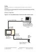
Setup This section describes how to set up the hardware and software needed to use the test application. Note: This tutorial was written using a Motorola Timeport® phone. Examples are provided in the instructions for setting up this phone. You may need to make different settings when using your own wireless devices. Hardware Connections Figure 1.
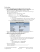
Test Set Setup For consistent results with PC network cards, turn off your PC before proceeding. 1. Turn on the test set or press the blue SHIFT key, then the green Preset key to reset it. 2. Press the SYSTEM CONFIG key. This displays the System Config Screen. 3. Verify the test application: GPRS Lab Application, E6701A, A.01.10 Note: version should be A.01.10 or higher. If not, some functions may be missing, or may cause firmware malfunctions. If the E6701A is not the active Test Application, switch it: 1.
Test Set’s Default Gateway: _________________________________ Set the Date and Time (Optional) If you set the correct date and time here, then protocol logs will include the correct date and time. 1. Press Instrument Setup (F1) key 2. Scroll down and set the Date in yyyy.mm.dd format (example: 2002.11.5 = November 5, 2002). 3. Press the knob 4. Edit the date, then press the knob to set it. 5. Scroll down and set the Time in hh.mm 24-hour format (example: 17.46 = 5:46 PM) as you did for the Date. 6.
IMPORTANT: The DUT IP Address and the Test Set ‘s LAN IP Address cannot be the same. Also, do not set the 4th set of numbers to 0; and do not set the 4th set of numbers greater than 254. 7. Press the knob to set the address. 8. Write down the address you entered: DUT IP ADDRESS _____________________________________________ Note that the entered DUT IP address must be on the same subnet as the Test Set. 9. Press the Close Menu (F6) key. PC Setup Turn on the PC. If already on, close any running applications.
b. In the scroll box labeled “The following network components are installed:” highlight your Ethernet network device. c. Select the Properties box d. In the TCP/IP Properties box, select the IP Address tab 1. Write down the original IP address here (in case you want to restore the original settings): PC’s original IP address: _________________________________ 2. Select “Specify an IP address” 3. Enter almost the same address as the Test Set’s LAN IP Address (see step 3.2.3.
5. In the Subnet Mask: field, we recommend you set the PC’s subnet mask to 255.255.255.0 6. Select OK, then OK again to exit the Network menu 7. If you made changes, a System Settings Change box will appear. Select the Yes box to Restart your PC. Windows 2000 This procedure assumes you are using a standalone PC (not connected to a network) using the Microsoft Windows 2000 operating system. Other PC configurations may use slightly different setups. 1. Go to the Control Panel 2.
Verify PC Settings On the PC, start the Microsoft Internet Explorer software. If you get a message saying “Work Offline” or “Try Again”, choose the “Try Again” box. If the PC tries to access a homepage, press the Stop icon. 1. In the browser’s Address field, enter the Test Set’s LAN IP address (from Test Set’s LAN IP Address from the Test Set Setup section above); then press Enter. Use the format http://111.222.333.222 as shown in the example below.
Verify that Your Device Will Perform an Attach If necessary, follow the manufacturer’s instructions to install the SIM into the device. 1.1. Turn on the phone or wireless appliance. Motorola Timeport phone example: The device should indicate service signal-strength bars (in the upper left corner of the display) within about 1 minute. It should also indicate the numbers “001-01” in the center of the display (this is the default test network number stored in the Test Set). 1.2.
e. Use the number keys to enter the PC IP address (see PC Setup above for your PC IP Address). This tells the phone where to find its primary server. i. Use the left arrow (*) and right arrow (#) keys to move among the numbers; use the C key to clear (or delete) a number. Note: on the Motorola Timeport phone, you must insert leading zeros so the IP address consists of 12 numbers. The decimal points between the numbers are entered automatically by the phone for this specific function.
3. Scroll to choose an unused http web address (or overwrite an old one). 4. Press the Menu (Edit) key 5. Under Enter URL: enter the following address: http://local/waplite.wml Editing addresses like this can be tedious on any menu-driven device, because you must switch among the alphabetic, numeric, and multiple symbol menus to enter all of the characters. Be patient. (Press the Menu key to switch among alpha, NUM, and SYM key sets.
E6701A Features Using a Direct Connection Between the PC and Test Set Verify the following: Setup has been successfully completed (See previous section Setup) Test set is on and displays the Call Setup screen. The wireless device is off. The PC is started, and displays a compatible browser window. Product Feature: Screen Image Capture You can retrieve a copy of the Test Set’s current screen. 1. On the PC, on the 8960 Web Control page, select the Get Image icon. 2.
4. For this tutorial, select GMM/SM and GSM_L3. Make sure the other observation points are NOT selected. 5. The Observation Points correspond to seven protocol layers you can log. Logging data will only be collected for layers that have been selected prior to the start of logging.
2. On the Save Web Page window, choose a directory. 3. To more easily find your log files, point to the file icon to Create New Folder, then select it. 4. For this tutorial, type this name for your New Folder: E6701A Demo Logs; then press the Enter key. 5. Double-click your new folder; E6701A Demo Logs will be shown in the Save in box above. 6. In the File name box, enter a different name for this log (for this tutorial, use Good Stuff1). Note: you must highlight the entire default filename to replace it.
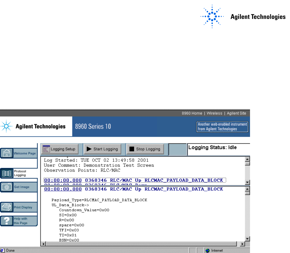
6. Watch the PC display after you press the Test Set Start / Stop Logging softkey (F1). Now turn the phone on. The PC display will update as new data is captured in the Test Set. (Also, at the beginning of each log, the “Log Started” time will change.) 7. On the Test Set, press the Stop Logging softkey (F1). Wait a few moments. The PC display will update as new data is captured in the Test Set. Product Feature: Ping Ping is a tool to help check system interconnects. Ping is only available in IP Data mode.
9. Press Stop Ping (F3) key 10. If you started a protocol log, stop it and look at the data. Pinging an Alternate Device (such as your PC on the LAN) Note: You cannot log an Alternate Device Ping because the data does NOT travel through the RF link, but only via the LAN. The Protocol Logging feature only captures data that passes over the RF link. 1. 2. 3. 4. 5. 6.
Product Feature: Data Channel This is one of the most useful and powerful features of the E6701A. The Test Set acts as a GPRS base station, for connection to one wireless appliance at a time, with complete connectivity through to outside GGSN’s. (A GGSN provides the gateway between the GPRS network and the public packet data network, also known as the Internet).
• Press the OK key 3. Scroll to http://local/waplite.wml or access this site from your wireless device. Motorola Timeport Example: • Press the OK key to Go. (The phone requests data from the device at the address above). 4. Watch the Test Set display: • At the bottom, in the Active Cell window, you can note the status will switch between PDP Active and Transferring as IP datagrams are sent back and forth between the phone and the WAPLite server on the PC.
2. On the Test Set, on the Call Setup screen, select Operating Mode (F1 key). 3. Scroll to Cell Off, and press the knob to select. 4. Select Cell Info (F6 key) 5. Select Cell Parameters (F2 key) 6. Change the Cell Parameters as desired. 7. Press Close Menu (F6 key) 8. Press Return (F6 key) 9. Press Operating Mode (F1 key) 10. Scroll to Active Cell, and press the knob to select. Timing Advance values can be sent to the DUT.
Appendix A: Installing a WAP Gateway into a PC Note: Agilent Technologies does not endorse or recommend the products listed below from various companies. We provide this information solely as a service to aid in this tutorial. Use them at your own risk. Agilent has done minimal testing with them in this application only. This information is subject to change without warning. Infinite WAPLite Gateway (by Captaris Inc.) For more company information: www.captaris.com For more product information: www.
Appendix B: Troubleshooting 1. If the wireless device will not attach, check that: 1.1. 1.2. 1.3. Cable loss is correctly specified in RF IN/OUT Amplitude Offset table The SIM is good and installed correctly Cell power is sufficient (increase it up to -35dBm to overcome interference, or if an indirect RF connection is used between the Test Set and phone) 1.4. Try Coding Scheme CS-1. Go to the Call Setup Screen; Call Parms column; Menu 2 of 4 (More key); Coding Scheme (F11 key) 1.5.
Parameters table to LLC Frame Check Sequence; change the table value to Corrupt. 2.2.3. It is possible that the mobile is capable but GMM is prioritised too low and the wireless appliance is unable to sustain the link. 2.2.3.1. To get around this we can change the BLER block polling period. This will allow the mobile to send the ACK/NACK less frequently(one negative result: TX measurements will be slower since the mobile is not transmitting every frame.) Go to call parameters, 1 of 4. 3.
5.3. PC: 5.3.1. Check that the network card (if present) is fully seated in the PC Card slot. 5.3.2. Check that the LAN IP address in the PC is the same as the Test Set’s LAN IP Address except for the 4th set of numbers (the last 3 digits). IMPORTANT: Do not set the 4th set of numbers to 0. Also, do not set the 4th set of numbers greater than 254. 6. The phone can’t access (browse) real Internet sites 6.1.
10.2.2. On the System Configuration screen, enter a valid address into the Default Gateway field 10.3. To permanently fix the problem: 10.3.1. Upgrade the Test Set firmware to a later revision. 10.3.2. This firmware can be obtained from the Agilent website at: www.agilent.com/find/8960support Copyright 2002 Agilent Technologies. All Rights Reserved. 10001809-E6701A Tutorial Direct Connection Page 29 of 30 Rev. 1.0; Feb.
Appendix C. Glossary BER BLER DUT GGSN GMM GPRS GSM GSM L3 HTML IMSI IP L1 LAB LAN LLC MAC MS PDP RF RLC SGSN SIM SM SNDCP TBF USF WAP WML Bit Error Rate Block Error Rate (Agilent proprietary connection mode – patent applied for) Device Under Test (typically, a cellular phone or wireless appliance) Gateway GPRS Support Node.