
User`s guide

Agilent PXT Wireless Communications Test Set
User’s Guide
89
CFI
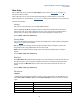
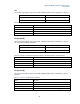
The Control Format Indicator (CFI) sets the number of OFDM symbols used for the PDCCHs in a subframe.
Transmission Bandwidth Configuration
Number of PDCCH Symbols per Subframe
> 10 RB (1.8 MHz)
CFI value
≤ 10 RB
CFI + 1
The CFI is mapped to the Physical Control Format Indicator Channel (PCFICH) in the physical layer.
Mode
BSE, FDD
Range
1 - 3
Preset
ACELL = 2 / BCELL = 2
Initial S/W Revision
6.1
Key Path
Mode > BSE > Mode Setup > More > PHY Settings
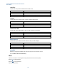
CFI (Normal SF)
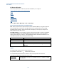
The Control Format Indicator (CFI) sets the number of OFDM symbols used for the PDCCHs in a subframe,
that is reserved for downlink transmission.
Transmission Bandwidth Configuration
Number of PDCCH Symbols per Subframe
> 10 RB (1.8 MHz)
CFI value
≤ 10 RB
1
CFI + 1
1. ≤ 10 RB is currently not supported as this is 1.4 MHz BW.
The CFI is mapped to the Physical Control Format Indicator Channel (PCFICH) in the physical layer.
Mode
BSE, TDD
Range
1, 2, or 3
Preset
ACELL = 2 / BCELL = 2
Initial S/W Revision
6.3
Key Path
Mode > BSE > Mode Setup > More > PHY Settings
CFI (Special SF)
The Control Format Indicator (CFI) sets the number of OFDM symbols used for the PDCCHs in a special
subframe.
See the CFI (Normal SF)
table above for reference.
Mode
BSE, TDD
Range
1,2
Preset
1
Initial S/W Revision
6.3
Key Path
Mode > BSE > Mode Setup> More > PHY Settings