
User`s guide

Agilent PXT Wireless Communications Test Set
User’s Guide
77
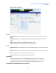
Field
Description
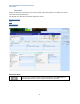
MeasId Represents the Measurement Identity as typically configured in an RRC
Connection Reconfiguration message.
RSRP Reference Signal Received Power – the value is an index. 3GPP 36.133,
section 9.1.4 shows the mapping here between the displayed value and the
measured quantity value in dBm. See More Information on RSRP
below and
under the Amplitude front-panel key description.
Note that this value can be used to determine path loss which can then be
applied as amplitude offsets. Refer to Amplitude Offsets on page 27
for more
information.
RSRQ Reference Signal Received Quality – the value here is an index. 3GPP 36.133,
section 9.1.7 shows the mapping between the displayed value and the
measured quantity value in dB.
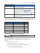
RSRP
RSRP values returned by the UE to the PXT represent a value somewhere within a 1dB range (see table below). For a
measured quantity value of 40, RSRP equals a measurement of the reference symbols between -99 and -100 dBm.
Reported value
Measured quantity value
Unit
RSRP_00
RSRP < -140
dBm
RSRP_01
-140 < RSRP < -139
dBm
RSRP_02
-139 < RSRP < -138
dBm
…
…
…
RSRP_95
-46 < RSRP < -45
dBm
RSRP_96
-45 < RSRP < -44
dBm
RSRP_97
-44 < RSRP
dBm
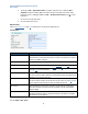
EXAMPLE: Calculating the expected RSRP using the PXT DL Amp Setting
If the path loss is zero, then the RSRP and the RSTP are equal.
Refer to the Amp > Amplitude section on page 6
for more information on the equation below.
RSTP power level = PXT Amplitude – 10 log
10
(number of resource elements in the cell
bandwidth)
1. Set Amp to the default value of −57 dBm.
For a 10MHz channel: RSRP = RSTP = −57 – 27.8 = −84.8dBm.
If there are no losses in the setup, the UE reports this -84.8 dBm value, as RSRP_56.
2. Always consider these variables when calculating RSRP:
a. For each dB of cable loss this RSRP value drops by 1dB.