
User`s guide

Agilent PXT Wireless Communications Test Set
User’s Guide
71
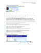
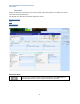
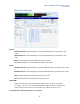
Interpreting Display Information
The indicators described below are those currently used by the PXT.
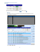
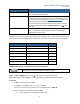
Shift: Shift in the input keypad.
N6061A: Logger is currently connected
OVF: Overflow. When this icon is lit up, it means the uplink power level is too high for the PXT to provide
accurate measurements. In order to achieve accurate power measurements, the OVF light should only come on
approximately 0-10 dB above the power level at which you wish to measure.
A-CELL: When in highlighted in yellow, this indicates A cell is active.
Note: If you set the reference level (Atten, Ref Level) of the attenuator high enough to achieve valid
measurement results, it may be too high for PRACH detection, the next time you wish to connect to the UE.
Therefore, it is recommended that you increase the attenuation if OVF is indicated while transferring DL data
(ensuring a correct decoding of the UL ACK/NACKs and preventing a reduced throughput reading), then reduce
it again to ensure you can connect when or if the UE drops the connection.
RMT: The instrument is being controlled remotely.
O.C: Oven cold (This indicator is highlighted ≤ 5 minutes after instrument is powered on.
B-CELL: When in highlighted in yellow, this indicates B cell is active.
INT: The instrument is using its built-in 10MHz reference.
EPC: The Evolved Packet Core is in use. You need this to be yellow for end to end IP data.
SINGLE: You are in single measurement mode versus continuous measurement mode.
10M: The instrument is using an external 10MHz reference.
TTCN: You are using TTCN. This is for protocol conformance testing.
HOLD: Disables all keys on the front-panel.
The displayed information above is described in the Scenario Information
section on page 143.