
User`s guide

Agilent PXT Wireless Communications Test Set
User’s Guide
31
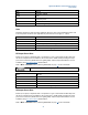
Mode
BSE, SA
Range
-100 dB to +100 dB
Preset
0 dB
State Saved Amplitude offset settings are preserved during power cycles or
instrument preset.
Initial S/W Revision
6.4
Key Path
Mode > Config > Amplitude Offsets
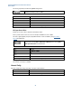
State
Determines whether the offset selected is applied (On/Off) to the offset you have highlighted and/or used
in the interpolation calculation when applicable. See pink column shown in Figure 2 – 1, above.
Mode
BSE, SA
Range
On | Off
Preset
Off
State Saved
State settings are preserved during power cycles or instrument preset.
Initial S/W Revision
6.4
Key Path
Mode > BSE/SA > Config > Amplitude Offsets
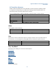
RF1 Output Power Offset
Enables you to specify an amplitude offset to compensate for a gain or loss between the RF1 Output and
the UE. For example: If there is a 40 dB loss, then set this value to -40 dB, thereby increasing the output
power of the instrument by 40 dB. This loss is applied globally. Frequency dependent definition of loss is
available by using The Tabular Method
described above.
Refer to Meas > Information section (calculating RSRP/RSTP) on page 77
for more information.
Maximum RF1 Output power is -10dBm.
Mode
BSE, SA
Range
–100 dB to +100 dB
Units
dB
Preset
0
Initial S/W Revision
6.0
Key Path
Mode > BSE/SA > Config > Amplitude Offsets
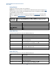
RF2 Output Power Offset
Enables you to specify an amplitude offset to compensate for a gain or loss between the RF2 Output and
the UE. For example: If there is a 40 dB loss, then set this value to +40 dB, thereby increasing the output
power of the instrument by 40 dB. This loss is applied globally. Frequency dependent definition of loss is
available by using The Tabular Method
described above.
Refer to Meas > Information section (calculating RSRP/RSTP) on page 77
for more information.