
User`s guide

Agilent PXT Wireless Communications Test Set
User’s Guide
30
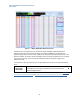
RF In/Out Offset
Selects the offset number (which is a point as shown on the graph in Figure XX, above) for which you wish
to specify frequency, offset, and state values. The offset selected is highlighted on the display. See red
column shown in Figure 2 – 1, above.
Mode
BSE, SA
Range
1 to 60
Initial S/W Revision
6.4
Key Path
Mode > Config > Amplitude Offsets
Frequency
Sets the frequency value for the offset you have highlighted in the Amplitude Offset Table. See navy blue
column in Figure 2-1, above.
For more information regarding how offsets are determined between specified frequencies, see Amplitude
Offsets Between Frequency Settings and Amplitude Offsets, Channel Bandwidths, and Center frequency.
Mode
BSE, SA
Range
350 MHz to 6.0 GHz
Preset
2.5 GHz
Staved Saved Frequency values are preserved during power cycles or instrument
preset.
Initial S/W Revision
6.4
Key Path
Mode > Config > Amplitude Offsets
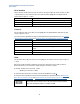
Offset
Sets the offset value in dB for the offset you have highlighted. See turquoise column of values in Figure 2-
1, above.
This feature provides the ability to implement path loss/gain compensation using a table of values for
specific frequencies. Loss is entered as a negative and gain is entered as a positive.
For example: +40 dB of loss is entered as – 40 dB.
+40 dB of gain is entered as +40 dB.
For more information about how to set offsets, see The Tabular Method on page 27.
For more information regarding how offsets are determined between specified frequencies, see Amplitude
Offsets Between Frequency Settings and Amplitude Offsets, Channel Bandwidths, and Center frequency.
Prior to software version 6.4, the PXT used negative values to represent a gain
and positive values to represent a loss. That sense offset has been reversed to
align with other Agilent products, for example the 8960.