
User`s guide

Agilent PXT Wireless Communications Test Set
User’s Guide
28
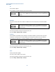
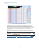
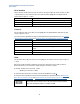
Figure 2 – 1: Offsets Applicable to Band 4 Frequencies
The table above is an example of how you would set the offsets applicable to Band 4 frequencies. It
displays the points for the upper/lower boundaries of the uplink, and likewise for the downlink. This
simplistic model provides a constant offset of -32dB on the received uplink path (32 dB of path loss), and -7
dB for the downlink. The result of the PXT’s downlink power is boosted by 7 dB (whether you are using RF1
or RF2 as the output port), and the received uplink signal has 32 dB of compensation applied to its
measurement result.
You would want to add more frequency points to fully describe the losses across the uplink and downlink
paths.
These offset values are also used by the Adaptive Attenuation feature on page 13
to determine the correct amount of attenuation required for the Idle and
Connected Adjuster values.
For more information regarding how offsets are determined between specified frequencies, see Amplitude
Offsets Between Frequency Settings and Amplitude Offsets, Channel Bandwidths, and Center frequency.