
User`s guide


Agilent PXT Wireless Communications Test Set
User’s Guide
225
Verify PXT Attenuation is set Correctly
The most common reason for a PXT BLER value is that the attenuation is set either too low or too high.
Ensure the OVF flag is clear. If the OVF alarm is raised, E2E data rates may show BLER
(StatDTX/NAKs/Packet loss).
Correct this by adjusting the Attenuation. Usually, setting Atten > Attenuation > to Adaptive
on the PXT
auto adjusts this for you. Make sure the UE supports Adaptive Attenuation.
Incorrect CFI Used for Channel Bandwidth
Using the incorrect CFI value for Channel Bandwidth may result in observing high BLER % and related E2E
or Closed Loop Power control issues. When the CFI is set to a smaller value, more symbols are used to
transmit PDSCH – this results in a lower coding rate and therefore a better chance that the transmission is
received correctly. However, it should be noted that there are a few configurations where setting too low a
value for CFI may cause problems – particularly for bandwidths less than or equal to 5 MHz. For example,
the aggregation level is fixed to 4 in TDD. This means that there is not enough space to transmit two
PDCCH messages unless CFI is set to a value higher than one. In this configuration, you would need to set
CFI while in TDD (Mode > BSE > Mode Setup > More > PHY Settings ) for both Normal SF and Special
SF to 2
or 3.
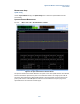
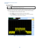
High EVM observed
If the Uplink E2E bit rate is much lower than expected on the UL, check the PXT SA LTE EVM readings
(Mode > SA > LTE > UL Demodulation > Error Vector).
Reaching the highest data throughput values on the UL require little or no channel coding protection on the
data. However, on a few devices it has been observed that the EVM value produced at higher power levels
is too high to allow successful channel decoding, unless some channel coding protection is implemented.
For these devices, it may help to reduce the EVM value by reducing the maximum power used by the UE.
The pMax setting (Mode > BSE > Mode Setup > More > RRC) on the PXT restricts this maximum.
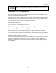
A typical setting that works is set like this:
After loading the scenario file and before running the simulator, override the RRC Setting by setting p-Max
On/Off and to On
. Then set the pMax value to approximately -20. Adjust the RF1 Attenuation accordingly to
a value around 35 dB, then establish connection by running the simulator and connecting the UE again.
Attempting Cat 4 setup / performance on a Cat 3 device at high end rates
Attempting to generate higher speeds than Cat3 (Cat4 setup) on a Cat3 only device results in packet loss /
BLER.
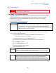
The following MCS/RB combinations for DL should be avoided for Cat3 devices:
Resource Blocks
I_MCS
Expected Mbps
> 68
28
> Cat 3 limits
> 81
27
> Cat 3 limits
> 84 26 > Cat 3 limits
Greater than 90
25
> Cat 3 limits
100 (0x01FFFFFF bitmap)
24
> Cat 3 limits