
User`s guide


Agilent PXT Wireless Communications Test Set
User’s Guide
223
7 Tips and Tricks
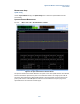
UE is not connecting.
The PXT may not be detecting the PRACH from the UE. Use the PXT default values for attenuation or set
Atten > Attenuation = Adaptive
.
The scenario file contains settings which define the UE’s preamble starting power and power ramping when trying to
establish a connection. It is important that they match the PXT receiver’s default expected power levels. The default
values have been selected to ensure most UEs can connect without difficulties relating to power levels. If these are
adjusted dramatically (by using the N6062A Protocol Message Editor software) it is likely the UE cannot connect because
either the UE is transmitting at the wrong power levels, or the PXT is set to the wrong attenuation values.
Using default conditions the PXT signals to the UE that it is transmitting at a high power (i.e. a similar level to that of a
typical eNB). However, the actual power transmitted by the PXT is much lower. The UE interprets this as a path loss and
adjusts its transmit power accordingly, hence the resultant uplink power transmitted by the UE will be within the default
input power range configured on the PXT.
It is recommended to use the default values because in the majority of cases, the default values will allow a
connection to be successfully established.
No IP Connectivity between PXT Server and UE
If you setup a UE <-> PXT <-> Server E2E IP connection but you find there is no connectivity between the PXT
Server and the UE (checked using ICMP ping), here are a few common checks to perform and workarounds
where applicable.
ICMP ping check in both directions
On UE-Host / UE: ICMP Ping PXT server IP address for connectivity.
On PXT server: ICMP Ping the UE IP address for connectivity.
When the PXT E2E link is functioning both above ICMP Pings are successful. The following checks should
be performed to troubleshoot and resolve.
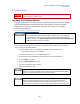
EPC enabled and connected
On PXT: Check EPC front panel software LED is enabled and running. The Software LED front panel “EPC”
should contain a border (enabled) and have yellow/green status (route to PXT server established).
A common mistake is to not setup the PXT Default Gateway correctly. If the PXT Default Gateway is not
present on the network, the EPC and E2E connectivity does not function.
If EPC is not enabled, restart UE connection with EPC enabled and valid/present PXT default gateway. In
lab conditions the PXT default gateway is usually the PXT Server PC used in E2E testing endpoint.