
User`s guide

Agilent PXT Wireless Communications Test Set
User’s Guide
222
Two ranges are specified as follows:
Range 1 (RP1):
F
UL_Meas
– F
UL_Low
≥ 3 MHz and F
UL_High
– F
UL_Meas
≥ 3 MHz
Range 2 (RP2):
F
UL_Meas
– F
UL_Low
< 3 MHz or F
UL_High
– F
UL_Meas
< 3 MHz
Where F
UL_Meas
refers to the sub-carrier frequency for which the equalizer coefficient is evaluated and
F
UL_Low
and F
UL_High
refer to each E-UTRA frequency band.
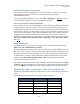
For both ranges (RP1 and RP2) the measurement displays the start and end subcarrier number, the
maximum and minimum power values, and the corresponding subcarrier’s number for which the max and
min have been calculated. In addition, the max peak to peak ripple for each range is displayed.
Measurement Setup
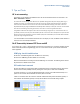
Access the following settings by selecting the Meas Setup front-panel key.
The Scale setting applies to both the Absolute Flatness and Differential Flatness graphics.
The Subcarrier setting moves the display marker. The marker result the subcarrier power appears in the
top right-hand corner of the display.
The Spectrum Flatness Slot Select will let the user select which slot in the radio frame to make the
measurements. For example, in TDD mode, you would select subframe #4.
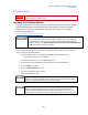
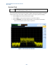
Measurement Results
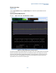
The display shows the equalizer flatness over the specified subcarrier range for RP1. In this case, the
measurement starts at −300 and ends at +299. Below the graph, summary results are displayed showing
RP minimum and maximum values, RP minimum subcarrier, Peak-to-Peak Ripple and the Relative
difference between RP1 and RP2.