
User`s guide


Agilent PXT Wireless Communications Test Set
User’s Guide
218
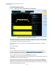
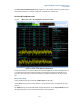
The blue outlined box overlaying the I and Q graphics indicates the ten subcarriers listed in the table. Use
the Subcarrier setting to set the index of the first subcarrier in the table.
The Power Spectrum Subframe Select setting enables you to select which subframe in the radio frame to
make the measurements. For example, in TDD mode, you would select subframe #2.
Map Information Measurement
Key Path:
Mode > SA > LTE > UL Demodulation > Map Information
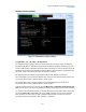
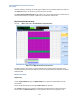
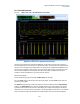
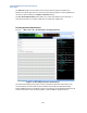
Figure 6-17: Map Information measurement
The Map Information measurement is a graphical display of the physical channels and signals in the
measured subframe. Use this measurement to see the resource grid indicating the allocations for PUCCH,
PUSCH and SRS.
Measurement Setup
Uplink Config
Use the Target Subframe setting in the Uplink Config menu to select the required subframe for this
measurement.
Access the following settings by selecting the Meas Setup front-panel key.
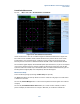
The X-Y Axis setting allows the graphic to be displayed with either symbols or subcarriers along the
horizontal axis. The Channel Table setting turns the legend at the bottom of the graphic on or off.