
User`s guide


Agilent PXT Wireless Communications Test Set
User’s Guide
215
Constellation Measurement
Key Path:
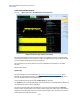
Mode > SA > LTE > UL Demodulation > Constellation
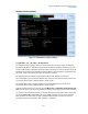
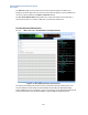
Figure 6-14: Constellation measurement
Use this measurement to view the constellation diagram for PUSCH and PUCCH reference signals, and
data. Numeric results for PRACH, PUCCH, PUSCH and SRS are also presented. These numeric results
include frequency error and symbol power, correlation accuracy and start time for the channel type
detected, parameter information for PRACH and PUCCH and EVM / CINR for PUCCH, PUSCH and SRS.
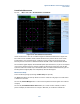
The Constellation graphic displays the demodulated symbols (data and reference) as points in the IQ plane.
In terms of the uplink receiver chain, reference symbols are taken directly from the FFT output but data
symbols are taken from the iDFT output. Demodulated symbols for PUSCH and PUCCH channel types and
Sounding Reference Signals (SRS) can be independently selected and displayed.
Measurement Setup
Access the following settings by selecting the Meas Setup front-panel key.
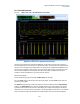
The Scale setting adjusts the scale per division on both the I and Q axes. The graphic has a fixed number
of 8 divisions on each axis.
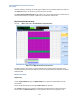
The menu key Channel Manager leads to a menu where the uplink channels and signals can be selected
for display.
The menu key Constellation Subframe Select enables you to select for which subframe you wish to
perform and display the measurement. For example, in TDD mode, you would select subframe #2.