
User`s guide


Agilent PXT Wireless Communications Test Set
User’s Guide
211
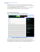
• Special Subframe Config. Index - determines how special subframes (which contain both
DL and UL) are composed as in how many symbols are used for DL and how many for UL.
These settings, available under Frame Structure (TDD) are grayed out when SA >
Mode Setup > Auto-Config = On.
.
Cell ID sets the physical (PHY) layer Cell ID. This PHY-layer Cell ID determines the Cell ID Group and Cell
ID Sector. There are 168 possible Cell ID groups and 3 possible Cell ID sectors; therefore, there are 3 * 168
= 504 possible PHY-layer Cell IDs.
The Meas Interval Start Subframe is the first subframe you wish to include in the measurement interval.
The Meas Interval Stop Subframe is the last subframe you wish to include in the measurement interval.
The nRNTI (Radio Network Temporary Identifier) setting is used by the PHY scrambling algorithms.
The IQ Inverse setting enables you to measure an inverted spectrum.
The Target Subframe setting provides the mechanism for selecting the subframe to measure. Target
Subframe selection assumes that the trigger occurs at the frame boundary.
PUSCH Settings
The same Resource Block (RB) allocation is applied to both slots in a subframe. The RB Start setting and
RB Size setting specify the index of the first RB and the number of RBs in the allocation.
The I_MCS (Modulation and Coding Scheme Index) specify the coding scheme of the allocation. For the
measurements to synchronize and demodulate correctly, it is only necessary that the modulation format
implied by this setting matches the modulation format of the signal. So, for a QPSK signal, the range of
I_MCS is 0 and 10; 11 to 20 for a 16 QAM signal.
The settings CQI Bit Length, RI Bit Length, and HARQ Bit Length refer to the number of bits allocated for
Channel Quality Indication, Rank Indication, and HARQ ACK.
The settings BetaOffset-CQI-Index, BetaOffset-RI-Index, and BetaOffset-Ack-Index are the layer 3
indices for the PHY parameters
CQI
offset
β
,
RI
offset
β
, and
ACKHARQ
offset
−
β
. Refer to TS 3GPP 36.331, 6.3.2
(PUSCH-Config) and TS 3GPP 36.213, 8.6.3 for further details. This group of settings, together with RV
Index and the redundancy version, are used by the Decoding Information measurement.
The PUSCH Hopping menu key accesses the PUSCH Hopping menu. Refer to TS 3GPP 36.213, 8.4 for a
description of the PUSCH Hopping Type, Hopping Mode, PUSCH Hopping Offset (
HO
RB
N
), N_sb (number
of subbands), Current_Tx_NB and Hopping Flag. The Hopping Flag setting refers to the information
content in the hopping bits. This information determines the allocation to be used in type-1 hopping (see
table TS 3GPP 36.213, table 8.4-2). Please note that PUSCH Hopping is not supported in BSE call
processing mode; therefore, all the above settings for PUSCH Hopping are relevant only for non-signalling
testing in SA mode.
Reference Signal Settings
The Sequence Hopping, Group Hopping, GroupAssignment PUSCH (∆ss), nDMRS(1) and nDMRS(2)
settings define the reference signal. These settings must match the applied signal in order for the
demodulation measurements to synchronize. Refer to TS 3GPP 36.211, 5.5 for a description of these
parameters.