
User`s guide

Agilent PXT Wireless Communications Test Set
User’s Guide
210
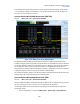
Scenario File Settings
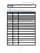
When Mode > SA > LTE > Mode Setup > AutoConfig is set to On, the settings shown in the table below
are automatically set to those same values determined by the currently loaded scenario file. (There must a
call in progress.)
Setting
Message Editor
Parameter
Message
Sounding RS SRS Applying Flag SIB2 – if soundingRS-UL_ConfigCOmmon = release = Off,
otherwise On
Ref Signal
Sequence Hopping
SIB2->groupHoppingEnabled
Ref Signal
Group Hopping
SIB2->SequenceHoppingEnabled
Ref Signal Group Assign
PUSCH
SIB2->groupAssignmentPUSCH
Ref Signal
nDMRS(1)
SIB2->cyclicShift
PUCCH
nCS-AN
SIB2>nCS-AN
PUCCH
nRB-CQI
SIB2->nRB-CQI
PUCCH
Delta PUCCH Shift
SIB2->deltaPUCCHShift
PUSCH
BetaOffsetCQIIndex
RRC Conn Setup->betaOffset-CQI-Index
PUSCH
BetaOffset-RI-Index
RRC Conn Setup->betaOffset-CQI-Index
PUSCH
BetaOffset-AckIndex
RRC Conn Setup->betaOffset-CQI-Index
PUSCH
UE Category
Emulator Mode->UE Category
Sounding RS
Cyclic Shift SRS
RRC Conn Setup->cyclicShift
Sounding RS
SRS Band Config*
SIB2->srs-BandwidthConfig
Sounding RS
SRS Band*
RRC Conn Setup->srs Bandwidth
Sounding RS
Transmission Comb*
RRC Conn Setup->TransmissionComb
Sounding RS SRS Hopping
Bandwidth*
RRC Conn Setup->srs-HoppingBandwidth
Sounding RS Freq Domain
Position
RRC Conn Setup->freqDomainPosition
Sounding RS
SRS Config Index
RRC Conn Setup->srsConfigIndex
*This parameter is also one that can be accessed via the front-panel.
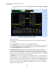
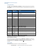
Uplink Configuration Settings
Access the uplink configuration settings by selecting the Mode Setup > UL Config. These settings must
match those of the applied signal in order to synchronize, demodulate, and measure correctly. Therefore
it is recommended that you set Mode Setup > Auto Config = On
. Refer to Auto Config for more
information.
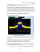
General Settings
Frame Structure (TDD only) enables you to define the following parameters:
• UL-DL Config. Index - determines which subframes are UL and DL, respectively