
User`s guide

Agilent PXT Wireless Communications Test Set
User’s Guide
207
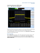
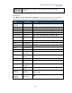
The Segment Side setting specifies whether the segment is a positive and negative frequency pair or just
one-sided. The Integration BW of each segment can be specified independently.
Having specified a segment, it is necessary to define what type of limit that segment should be tested
against. This is done through the Fail menu. The default limit type is Absolute as this is the type of limit
specified by the LTE standards, but a limit may be specified to be Relative to the carrier or a combination
of Relative and / or Absolute limits. The Absolute and Relative limits are specified separately through the
Absolute Start Power / Absolute Stop Power and Relative Start Power / Relative Stop Power settings.
Provision of Start and Stop Power pairs allow limits to be set as a linear function of frequency, if required.
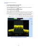
Adjacent Channel Leakage Ratio (ACLR) Measurement (FDD/TDD)
Key Path:
Mode > SA > LTE > ACLR
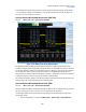
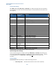
Figure 6-12: ACLR measurement
The ACLR measurement determines the ratio of Channel Power to power leaked into adjacent channels.
The adjacent channels can be either E-UTRA channels or UTRA channels. The standards require that both
are measured.
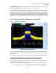
The measurement displays a graphic of the power spectrum of the signal with histograms representing
channel powers superimposed. The key measurement results are summarized in a table.
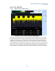
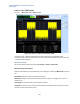
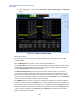
Adjacent Channel Leakage Ratio (ACLR) Measurement (TDD example)
For TDD, special care must be taken with regard to the UL-DL configuration in order to be certain you are
measuring an uplink subframe. For example, to measure ACLR of subframe 2 ensure these settings are
selected in order to obtain valid measurement results:
1. Set the target subframe = 2 by pressing Mode Setup > Uplink Config > Target Subframe. 2,