
User`s guide

Agilent PXT Wireless Communications Test Set
User’s Guide
205
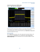
As an example of how these settings are used, if there are three measurement intervals of Gate Length
1 ms, a Gate Delay of 500 us and a Gate Delta of 2 ms, the three measurement intervals are .500 ms to
1.5 ms, 2.5 ms to 3.5 ms and 4.5 ms to 5.5 ms.
Spectrum Emission Mask (SEM) Measurement (FDD/TDD)
Key Path: Mode > SA > LTE > Spectrum Emission Mask
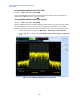
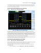
Figure 6-10: SEM measurement (FDD Example)
The SEM measurement considers the Power Spectrum at various frequency offsets from the carrier.
Contiguous frequency offsets are grouped into segments which are usually defined as pairs on either side
of the carrier, although a segment can be specified to be on one side of the carrier or the other. Segments
are then defined in terms of a start and stop offset frequency; an integration BW and whether the
measured spectrum power should be tested against an absolute or relative limit value. A set of segments
so defined constitutes a mask. You may specify a number of different masks.
The measurement displays a graphic of the spectrum emission mask (showing measured spectrum power
and limit values) and a table summarizing the key measured values.
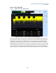
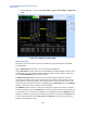
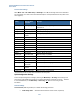
Spectrum Emission Mask (SEM) Measurement (TDD)
Key Path:
Mode > SA > LTE > Spectrum Emission Mask
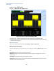
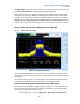
Below, the SEM measurement using TDD is displayed. For TDD, special care must be taken with regard to
the UL-DL configuration in order to be certain you are measuring an uplink subframe.
In this example, subframe 2 is measured. Ensure these settings are selected in order to obtain valid
measurement results:
1. Set the target subframe = 2 by pressing Mode Setup > Uplink Config > Target Subframe. 2,