
User`s guide

Agilent PXT Wireless Communications Test Set
User’s Guide
191
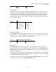
RF2 Modulation
On
Source Level
The same level can be set on both sources using the Amplitude setting or the two sources can be set to
different values using the RF1 Amplitude or RF2 Amplitude settings. Each source may be offset for path
loss or gain using the RF1 Output Power Offset and RF2 Output Power Offset. The source power will be
increased by the value of the power offset. That is, positive values for power offsets are regarded as
external cable losses and the actual source power is adjusted so that the requested power appears at the
input to the device under test.
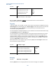
Key Path:
Amp
Preset:
Source 1 amplitude
Source 1 offset
Source 2 amplitude:
Source 2 offset
–57 dBm
0 dB
–57 dBm
0 dB
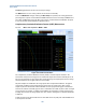
Receiver Port Setup
The Input Mode setting determines whether the receiver input is taken from the internal down-converted
RF or externally from the rear panel. If the rear panel is selected as the input mode, the Input Source can
be specified to be an IF signal at 76.8 MHz or an IQ baseband signal.
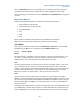
Key Path:
Config > RF Setup > RF Input Control
Preset:
Input mode:
Internal
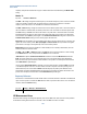
Receiver Level
Select Atten > Ref Level to set the receiver level. This setting is applied to both receivers (if second
receiver option is available). To set the two receiver levels to different values use the RF1 Ref Level and
RF2 Ref Level menu keys. The Ref Level and the Scale/Div settings are applied to all the Power Spectrum
and Power vs. Time displays.
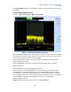
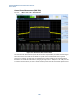
If the reference levels / attenuators are incorrectly set so that an overload condition occurs, the red OVF
warning indicator in the top right of the display will illuminate. If this happens, increase the reference level
or attenuation until the warning indicator turns off.
External loss/gain can be compensated for with the RF1 / RF2 Input Power Offset. To compensate for a 6
dB path loss to RX1, for example, set RF1 Input Power Offset to -6 dB.