
User`s guide

Agilent PXT Wireless Communications Test Set
User’s Guide
190
Frequency
Sets the uplink or downlink frequency, or both, for the system. Refer to the
Freq
– Key Menu 1 in the Front-panel and Menu Keys chapter for more information.
Key Path:
Freq
Preset:
UL/DL Frequency:
UL Frequency:
DL Frequency:
1.95 GHz
1.95 GHz
2.14 GHz
Range:
E6621-503: 350 MHz – 3 GHz
E6621-506: 350 MHz – 6 GHz
Default Units:
GHz
Notes:
The same receiver is used for measurements and link maintenance.
Center (UL/DL) Freq (TDD only)
Sets the uplink and downlink frequency to the same value.
Center (UL) Freq
Sets the uplink frequency.
Center (DL) Freq
Sets the downlink frequency.
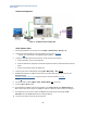
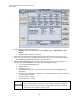
Source Port Setup
RF Output Control
The PXT has one receiver and two sources. Source1 can be routed to either RF1 Output or
RF1 Input /Output. Source 2 is always routed to RF2 Output. The settings RF1 Front Panel Output and
RF2 Front Panel Output in the RF Output Control menu determine this routing. RF2 Front Panel Output is
grayed out.
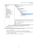
The sources’ baseband signals normally connect internally to the RF signal generators. However, the
baseband signals (balanced I and Q signals) may be routed to the rear panel to enable UE baseband-to-
baseband testing. The RF DL Output setting in the RF Output Control menu determines the baseband
routing.
Source power and modulation can be turned On/Off using the RF and MOD keys above the ports. LEDs
indicate the power and modulation state of each source.
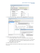
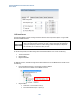
Key Path:
Config > RF Setup
Preset:
RF Output control 1
RF Output Control 2
RF Input Control
RF1 Power
RF2 Power
RF1 Modulation
TRX
TX
Internal
On
On
On