
User`s guide

Agilent PXT Wireless Communications Test Set
User’s Guide
174
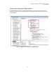
3. The EPC of the two PXTs needs to be “connected”. Therefore, you need to connect the Slave EPC to the
Master EPC. In the Slave PXT, enter the EPC address of the Master and connect.
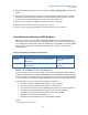
a. On Slave PXT, select Config > Network Settings > EPC Setup > PXT Connections > MASTER
PXT IP Address #1 (192.168.1.60 in this example)
b. You don’t need to change anything on the Master PXT EPC.
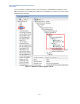
4. The Gateway setting must be the same on the Master PXT as the EPC setup menu.
(Note: This is the same IP address as the destination server or the other end of LTE pipe. This is verified
when you ping from the UE to the destination server to ensure you have IP continuity or that you can
actually pass data from the UE.)
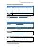
a. Set the gateway IP address on the Master PXT to: 192.168.1.230 by selecting Config > Network
Setup > IP Setup > Gateway
5. Security Settings must be the same on both PXTs.
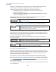
a. Select Mode Setup > More > Security Settings. Set Security to On.
b. Then set all security parameters properly, based on the UE under test.
Handover Test Steps
1. Press Preset.
2. On the Master PXT, select and load the scenario file that you downloaded with your new PXT software
named, “FDD_CellA_v6.4” by selecting Mode > BSE > Mode Setup > Call Scenario.
3. Set Master EPC to Embed
by selecting Mode Setup > EPC = Embed.
4. Set Slave EPC to Off by selecting Mode Setup > EPC = Off.
5. Run scenario file in Master by selecting Mode > BSE > Emulator Mode = Run.
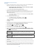
6. Connect PXT EPC Slave to Master EPC by selecting Config > Network Settings > EPC Setup > External
EPC = Connect
(the EPC indicator should say EXT with a white background. This means the slave is using
an external EPC: the EPC of the master.)
•
If you need to stop and then run the emulators for Master or Slave, it’s
important that you always run the Master prior to the Slave and that you always
stop and start them both, in order to maintain connection to the EPC.
7. Load and run the scenario file named: “FDD_CellA_v6.4“in the slave PXT.
You must see “Add Cell 2” in the message view of the EPC or you have reversed
steps 6 and 7.
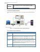
8. Turn on UE.
9. Force UE to connect to master by ensuring the slave RF power is Off. (Green CON status indicator light
should be lit.)
10. EPC indicator light is highlighted in yellow on Master: This means that a ping from the UE to the destination
server is working.
11. Now you can either perform a reselection by turning the master RF power off and the slave RF power on or
you can perform a cell redirection by sending a handover message to the UE. The handover message has
already been configured in the loaded scenario files.